L L1 L2 W1 W2 W H H1 N
1007
1007
1081
1071
1071
1054
1054
1129
1138
1138
1195
1195
1276
1311
1311
588
701
991
1005
1185
356
431
595
465
616
801
914
1204
1106
1286
272
272
272
390
390
142
163
202
227
229
Φ144
Φ144
Φ198
Φ244
Φ244
N1
136
136
136
195
195
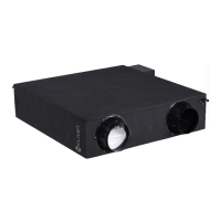
Fig. 3-4
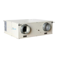
Fig. 3-5
Table 3-1
Key dimensions of the unit and air duct installation. (See the following pictures Fig.3-4~3-7 & Table 3-1 )
Door
Electric
control
box
By-pass
system
Exhaust air outlet
Fresh air inlet
Return air inlet
Supply air outlet
Lifting lug
N
N1
H
W
W1
L
L1
L2
W2
H1
L1
L
L2
N1
N
W
Door
Electric
control
box
Return air inlet
Supply air outlet
Exhaust air outlet
Fresh air inlet
H1
W2
W1
H
195
Φ244230
390
1526
7641431
1138
1311
1071
Communication wiring between the indoor and outdoor units
The HRV and outdoor units communicate via the RS485 serial port.
The communication wiring between the HRV and outdoor units should be connected one unit after
another in a daisy chain from the outdoor unit to the final HRV unit. And the shielded layer must be
properly grounded, and a build-out resistor must be added to the last HRV unit to enhance the stability
of the communication system.
Incorrect wiring such as a star connection or a closed ring will cause instability of the communication
system and system control anomalies.
Use a three core shielded wire (greater than or equal to 0.75 mm2) for the communication wiring
between the indoor and outdoor units. Make sure the wiring is connected correctly. The connecting lead
for this communication wire must come from the master outdoor unit.
All shielded wiring in the network are interconnected, and will eventually connect to earth at the same
point " ”.
By-pass
system
(Unit:mm)
Communication wiring between the indoor unit and wired controller
The wired controller and the indoor unit can be connected in different manners, depending on the forms of
communication.
1. For a bidirectional communication mode:
Use 1 wired controller to control 1 indoor unit or 2 wired controllers (one master and one slave
controller) to control 1 indoor unit.(see Fig.4-4)
Use 1 wired controller to control multiple indoor units or 2 wired controllers (one master and one slave
controller) to control multiple indoor units. The maximum number of connections is 16.(see Fig.4-5)
2. For single direction communication mode:
Use 1 wired controller to control 1 indoor unit
The X1/X2, D1/D2 ports on the sides of the main control board and single direction communication port
are for different types of wired controllers.
For the specific connection method, refer to the instructions in the corresponding wired controller
manual to carry out the wiring and connections.
Handling the Electrical Wiring Connection Points
Once the wiring and connections are done, use tie straps to secure the wiring properly so that the
connection joint cannot be pulled apart by external force. The connection wiring must be straight out so
that the cover of the electrical box is level and can be closed tightly.
Use professional insulation and sealing materials to seal and protect the perforated wires. Poor sealing
may lead to condensation, and entry of small animals and insects that may cause short circuits in parts
of the electrical system, causing the system to fail.
Model
HRV-2B-Mi D200~D400
HRV-2B-Mi -D500~D1000
HRV-2B-Mi -D200
HRV-2B-Mi -D300
HRV-2B-Mi -D400
HRV-2B-Mi -D500
HRV-2B-Mi -D800
HRV-2B-Mi -D1000
 Loading...