13
Installation
The wiring diagram of the outdoor
unit is located inside the terminal
box cover.
Cover
Fig. 7
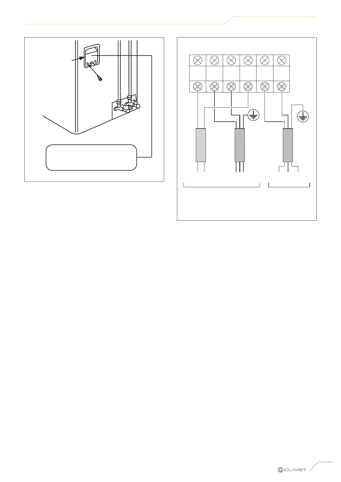
4 Match the colours/labels of the cables to the labels
on the terminal block, then screw the U-shaped wire
terminal of each cable firmly to the corresponding
terminal block.
Morsettiera unità ESTERNA
dalla morsettiera
dell’unità INTERNA
segnale alimentazione
230V~50Hz
PENL
W
S L N
1(L) 2(N)
OUTDOOR unit terminal block
power supplysignal
from the terminal block of
the INDOOR unit
Fig. 8
5 Check that all connections are stable, then wrap the
cables to prevent rainwater from entering the terminals.
6 Attach the cable to the unit using the cable clamp.
Screw the cable clamp on firmly.
7 Insulate unused cables with PVC insulation tape.
Arrange them so that they do not touch electrical or
metal parts.
8 Replace the cover on the side of the unit and screw
it back on.
 Loading...