17
Installation
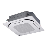
Water level
Fig. 18
l
WARNING
Check that the indoor unit is horizontal.
The unit has a drain pump and a float switch. If
the unit tilts in the opposite direction to that of
the condensate flow (with the drain pipe side
raised), the float switch may not work properly
and cause a water leak.
11 Use the hexagonal nuts on the four assembly hooks
to adjust and ensure that the unit’s casing is level.
12 Adjust the position of the unit’s casing and ensure that
the gap with the ceiling is even on all four sides.
13 Once the position of the casing has been adjusted,
tighten the nuts to secure the unit.
NOTE FOR INSTALLATION IN NEW BUILDS
Main body
Installation
template
Fig. 19
l
WARNING
When the unit is to be installed in a new build,
the hooks may already be fitted in the ceiling.
In this case, check that the hooks have not
come loose due to concrete shrinkage.
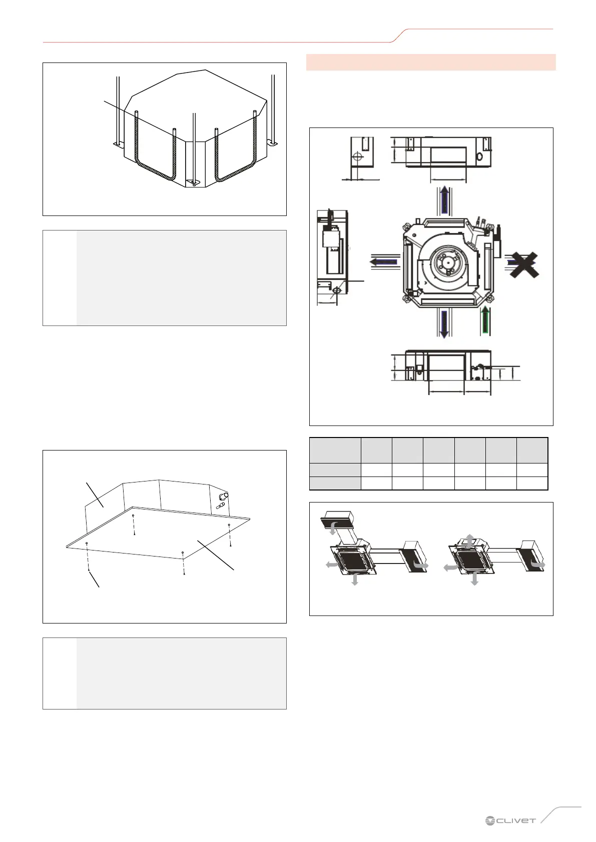
2.4.3 Derived ducts
These units can be fitted with small ducts for air
conditioning a small room nearby.
The units are designed for ducting on 3 sides: the side
with the electronic expansion valve cannot be ducted.
Distribution
duct
Distribution
duct
Distribution
duct
Outdoor
air
A
A
E
F
B
B
D
C
C
58
Ø75
258
Fig. 20
Model
A
(mm)
B
(mm)
C
(mm)
D
(mm)
E
(mm)
F
(mm)
2.8-8.0 kW 350 85 107 126 121 145
9.0-14.0 kW 350 155 107 197 121 145
Fig. 21
– If only one air duct is connected:
for 5.6~8.0 kW models, the volume of air in the
duct is about 300~360 m
3
/h.
for 9.0~14.0 kW models, the volume of air in the
duct is about 400~640 m
3
/h.
The air duct must not be longer than 2 metres.
 Loading...