Do you have a question about the CLIVET Versatemp EQV-X and is the answer not in the manual?
Provides unit installation, use, and maintenance instructions.
Covers general guidelines, safety, and user training for unit operation.
Important notes for users regarding manual keeping, data logging, and assistance.
Details on identifying the unit via serial number labels and components.
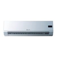
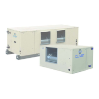
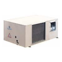
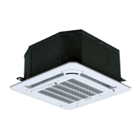
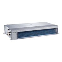
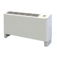
Overview of the VERSATEMP EQV-X as a heat pump.
Lists available configuration, air side, hydraulic, and electric circuit accessories.
Safety and general information before unit reception.
Procedures for checking unit delivery for damage and correctness.
Guidelines for safely lifting and handling the unit with packaging.
Steps for safely removing packaging from the unit.
Safety and general considerations for unit positioning.
Design considerations and standards for unit placement.
Instructions for wall mounting uncased units.
Instructions for floor mounting uncased units.
Details on floor fixing for cased units with adjustable feet.
Guidelines for optimal thermostat placement for comfort and efficiency.
Recommended clearances for unit operation and maintenance.
Safety, general info, and components for water connections.
Details on connecting tubing to unit attachments and sealing.
Proper connection of condensate discharge to prevent issues.
Components of the standard unit's water circuit.
Description of plumbing assembly for constant flow rate loops.
Description of plumbing assembly for variable flow rate loops.
Details on modulating valve for systems with disposable water.
General safety and electrical connection guidelines.
Information regarding power supply connections and cable management.
Details on customer-specific electrical connections and ventilation control.
Wiring instructions for thermostat connection up to 10 meters.
Wiring instructions for thermostat connection up to 200 meters.
Configuration for connecting multiple units in a master-slave network.
Details on Modbus network supervision module and settings.
Information on the BacNet gateway kit for communication.
Information on the LonWorks gateway kit for communication.
Preliminary checks and procedures before unit start-up.
Explanation of control panel buttons, display icons, and functions.
Instructions for turning the unit on and off.
How to change the operating mode (Cooling, Heating, Auto).
How to adjust fan speed settings (Low, Medium, High, Auto).
How to increase or decrease the setpoint temperature.
How to adjust ECO and COMFORT settings for energy saving or comfort.
Procedure for resetting unit alarms after identifying the cause.
How to lock or unlock the control panel buttons.
How to visualize unit status and parameters.
Access and modification of installer-specific parameters.
Setting the current hour and day for the unit's clock.
How to program time bands for automatic operation.
How to enable or disable scheduled operations.
List of unit status parameters and their descriptions.
Table of unit parameters accessible for modification.
List of all possible alarms and their reset methods.
General principles and benefits of unit maintenance.
Recommended schedule for unit inspections based on usage.
Advice on creating a booklet for recording unit interventions.
Procedures for placing the unit in standby mode for long inactivity.
Checks for fan fixing, bearings, and noise.
Importance of cleaning the water exchanger for thermal exchange.
Importance of cleaning the air exchanger battery for thermal exchange.
Recommendations for cleaning condensate discharge to prevent blockages.
Steps for checking and cleaning the water filter.
Importance and procedure for cleaning and replacing air filters.
Step-by-step guide for extracting the fan unit.
Reference for unit removal procedure.
Checklist of periodic controls for unit maintenance.
Detailed dimensions for the in-view vertical unit.
Diagrams showing pipe work arrangements for different loop types.
Detailed dimensions for the vertical flush-mounted unit.
Comprehensive technical data for various unit sizes.
Cooling and heating operating limits based on air and water temperatures.
Sound power and pressure levels for different fan speeds and sizes.
Specifies that only qualified personnel can operate on the unit.
General overview of common risks not controllable by the manufacturer.
Defines the area accessible only with deliberate removal of protections.
Risks associated with improper handling and lifting of the unit.
Risks related to incorrect unit installation.
Potential hazards like burning smells, smoke, or contact with components.
Risks associated with electrical connections, earthing, and internal parts.
Risks of injury from contact with moving parts like fans.
Risks associated with refrigerant gas leaks, pressure, and heat sources.
Risks from leaks in tubing, attachments, or cut-off parts.
Procedures for safely disconnecting the unit and recovering fluids.
Guidelines for sending the unit to authorized dismantling centers.
Information on compliance with waste electrical and electronic equipment directives.
| Brand | CLIVET |
|---|---|
| Model | Versatemp EQV-X |
| Category | Air Conditioner |
| Language | English |