M03I40M7-03 15/11/07 page 15
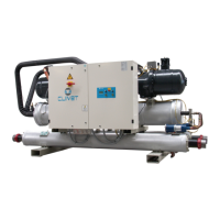
DIAGRAM OF RECOMMENDED USE SIDE CONNECTION
Depending on the type of machine and the selected setup, some components may be integrated into the unit.
P
9
11
14
8
F
2
3
5
12
7
6
4
8
1
10
13
P
7
1. Charged system pressure switch
2. vent
3. circulating pump / pump
4. expansion tank
5. safety valve
6. flow switch
7. pressure switch / thermometer
8. filter
9. filling valve
10. antivibration joints
11. user side exchanger
12. Differential pressure switch
13. Discharge cock
14. inertial storage tank
The accumulation tank is necessary in the event of the following:
• the water in the system is very low
• the unit will not be used in a private house (in an industrial process or other)
RECOVERY EXCHANGER
OPTIONAL - The unit can be equipped with exchangers to
recover the condensation heat.
The recovery can be:
TOTAL
• with 100% recovery of the condensation heat
• the thermoregulation is performed by CLIVET control
system
PARTIAL
• with 20% recovery
• The customer is responsible for the management of the
circulation pump, valves, thermostats, etc
The recovery input water must not be below 25°C, in the
event that, wrongful operations and breakages of the unit
can occur .
Water connections must be performed carefully as for the
evaporator (filter, circuit washing, etc) .
Perform all necessary interventions to avoid the RISK OF
FREEZING (tubes insulation, emptying of circuit, addition of
glycol, anti-freeze resistances) .
Water temperature can reach high temperatures (up to
100°C), therefore:
• avoid the RISK OF BURNS by adopting the necessary
precautions (insulation of tubes, temperature detecting
station on water if the sanitary use is foreseen, etc)
• Install safety valves and specifically dimensioned
expansion tanks in the hydraulic circuit.
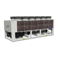
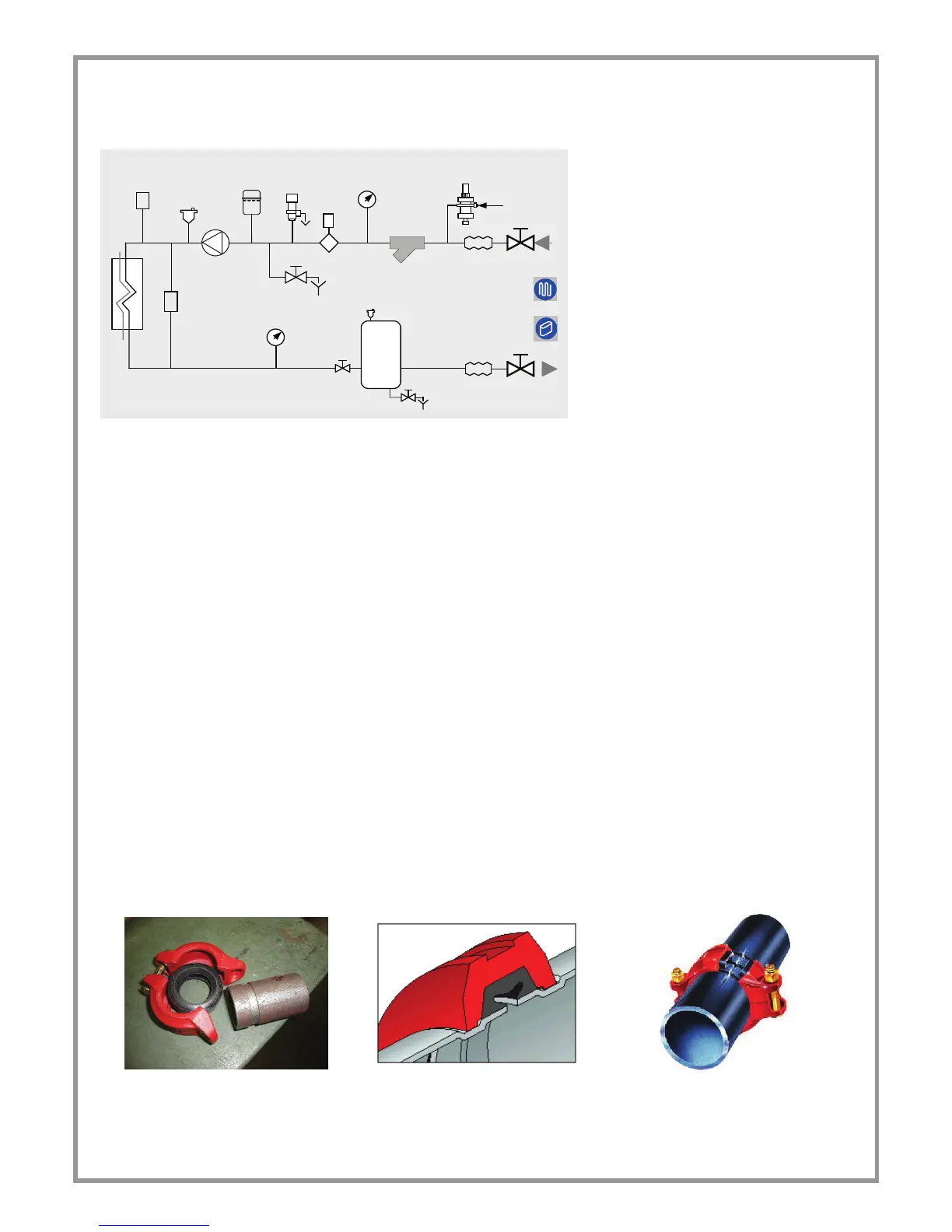
VICTAULIC CONNECTIONS
1. Take away the supplied connection union by acting on the connection joint Victaulic.
2. Weld the union to the installation pipe.
3. Perform the connection between the installation pipe and the evaporator, using the joint.
Do not weld the system pipe with the Victaulic connection joint attached.
The rubber gasket might be irreparably damaged
 Loading...