57
Electrical connections
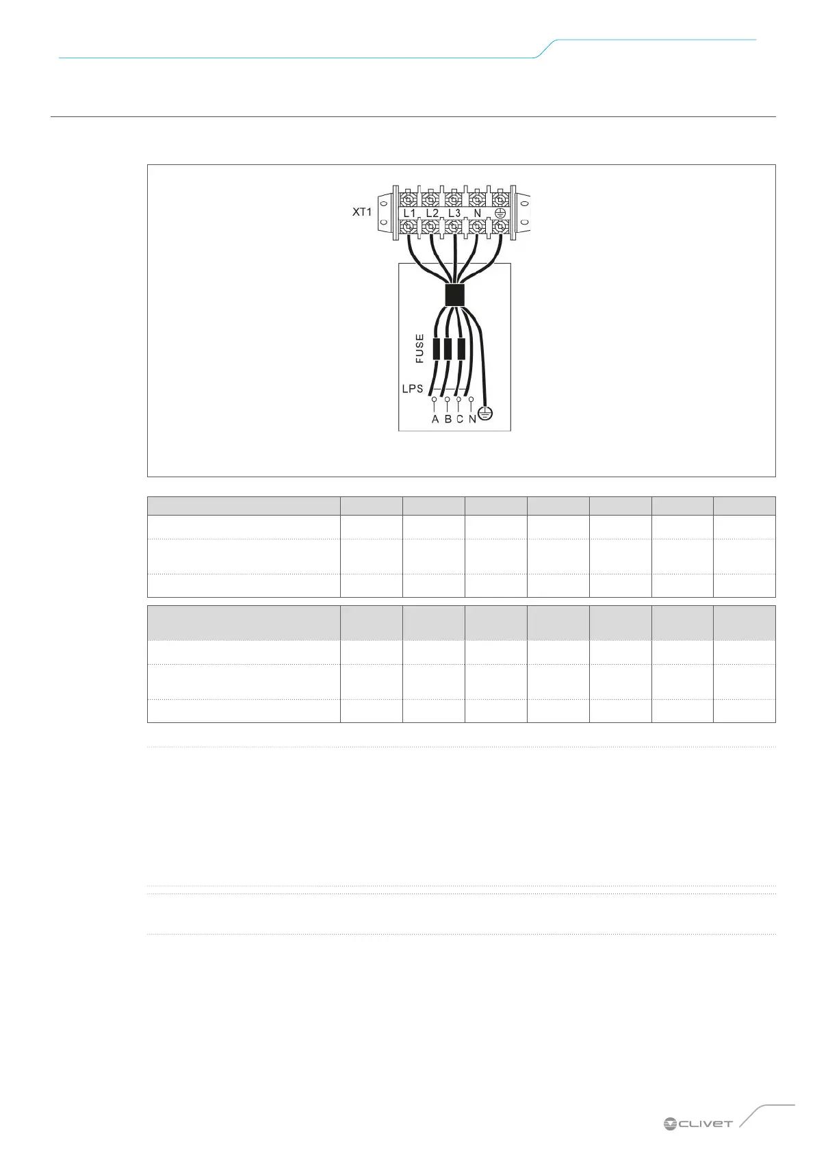
7.5.2 Electrical connection specifications
Compressor compartment and electrical parts: XT1
Fig. 50
Size 2.1 3.1 4.1 5.1 6.1 7.1 8.1
FLA (A) 12 14 16 17 25 26 27
Maximum tripping of
protections (A)
25 25 25 25 35 35 35
Cable cross-section (mm
2
) 2.5 2.5 4 4 6 6 6
Size 6.1 3~
7.1
3~
8.1
3~
9.1 10.1 12.1 14.1
FLA (A) 10 11 12 21 24.5 27 28.5
Maximum tripping of
protections (A)
16 16 16 25 25 32 32
Cable cross-section (mm
2
) 2.5 2.5 2.5 6 6 6 6
L
NOTE
The design of the power supply line and its protections is to be provided by the system’s
electrical designer. The design standards dier depending on the country of installation,
the length of the lines, the distance to the protection devices and the quality
of the power supply. The minimum cross-section indicated for cables is not necessarily the recommended
one.
The values given are maximum values. Refer to the electrical data for the exact values. For the sizing values
of the external protections, refer to the rated electrical data (bill, labels).
O
WARNING
The earth leakage circuit breaker must be a 30 mA (<0.1 s) fast tripping type.
Procedure for all connections
• Connect the cable to the appropriate terminals as shown in the diagram.
• Secure the cables with cable ties at the appropriate attachment points to prevent tension.
 Loading...