M02R40C8-00 29/07/08 page 16
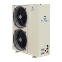
DIAGRAM OF RECOMMENDED USE SIDE CONNECTION
Depending on the type of machine and the selected setup, some components may be integrated into the unit.
The accumulation tank is necessary in the event of the following:
• the water in the system is very low
• the unit will not be used in a private house (in an industrial process or other)
P
9
11
14
8
F
2
3
5
12
7
6
4
8
1
10
13
P
7
1. Charged system pressure switch
2. vent
3. circulating pump / pump
4. expansion tank
5. safety valve
6. flow switch
7. pressure switch / thermometer
8. filter
9. filling valve
10. antivibration joints
11. user side exchanger
12. Differential pressure switch
13. Discharge cock
14. inertial storage tank
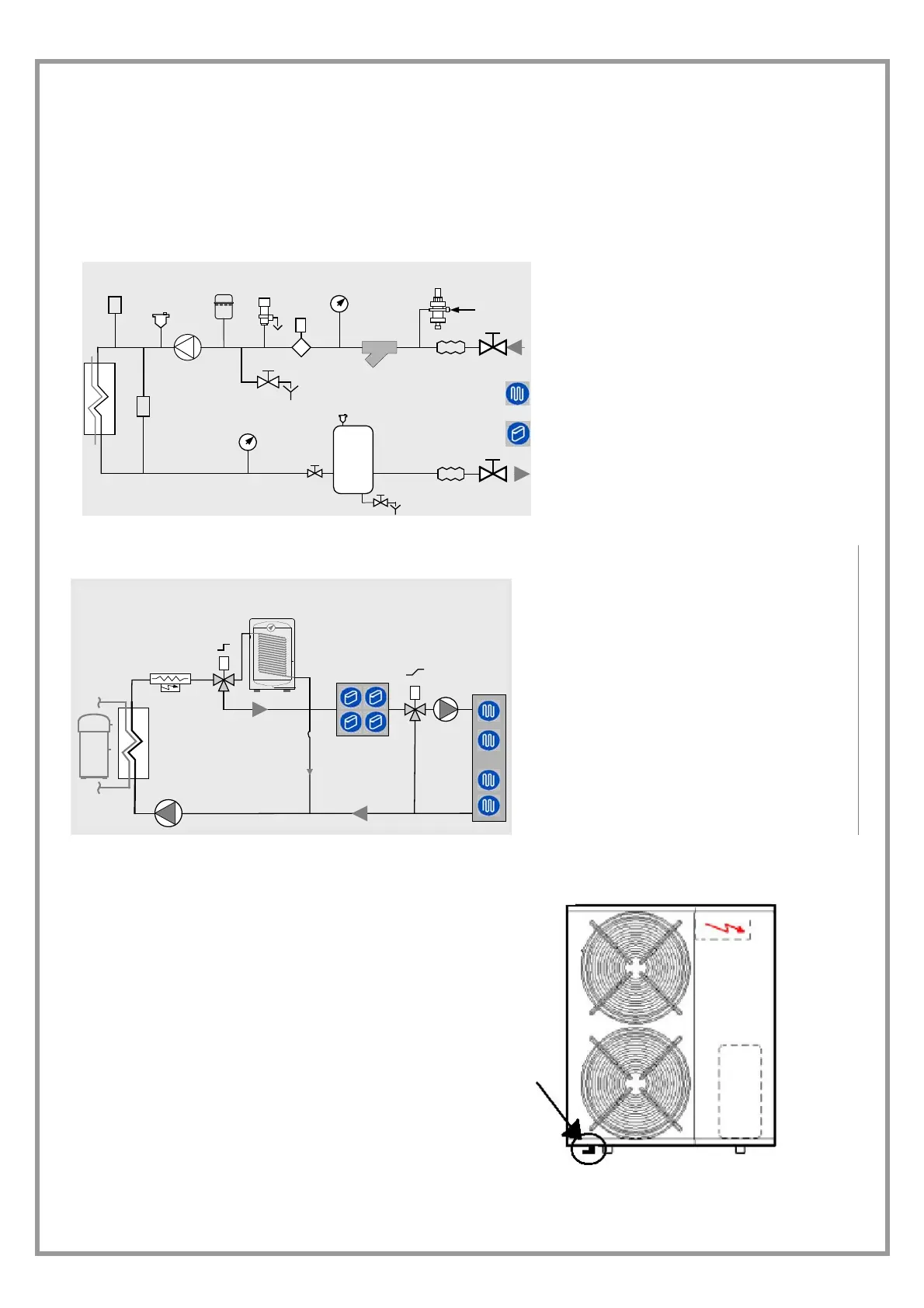
USE SCHEMA
8
1
2
3
4
5
6
7
8
1. Heating integration
2. 3-ways ON-OFF domestic hot H2O
3. domestic hot water boiler
4. fancoil
5. 3-ways radiant panels
6. radiant pump
7. radiants
8. pump / circulating pump
for more details see the ELECTRICAL DATA
section
WINTER CONDENSATION
When a heat pump is running it produces a considerable
amount of water due to the defrosting cycles of the
external coil.
The condensation must be eliminated in a manner to
avoid wetting pedestrian areas.
With extensive very cold outdoor temperatures,
condensation could freeze and block the flow, causing a
slow build-up of ice;
therefore special attention must be paid to eliminating
condensation, raising the unit off the ground and
evaluating whether antifreeze elements should be
installed.
For units with condensation trays, refer to the dimensional
diagrams to calculate the condensation discharge.