M02R40C8-00 29/07/08 page 19
FUNCTIONAL CONNECTIONS
FOR ALL THE CONNECTIONS MAKE REFERENCE TO THE ELECTRICAL PANEL SUPPLIED WITH UNIT
Use voltage-free remote control devices that are suitable to commutate very low loads (12V, 10mA)
Few inputs must be activated by configuration parameters whose access is reserved to authorized assistance centres (in order
to avoid unauthorized modifications)
1. remote ON / OFF
2. remote SUMMER / WINTER
3. remote SECOND SET POINT (ECO )
4. Machine OPERATION / SHUTDOWN SIGNAL
5. REMOTE KEYPAD
6. ELECTRIC INTEGRATION during heating
7. coupling with BOILER
8. DOMESTIC HOT WATER
9. RADIANT PANELS
10. SET POINT COMPENSATION for outside temperature/enthalpy
11. SET POINT COMPENSATION with 4-20 mA signal
12. interface via RS485
1. ON / OFF FROM REMOTE CONTROL
Generally the unit is delivered with bridged terminals; if the control is not used, the bridge should not be removed
2. CHANGING FROM SUMMER TO WINTER USING THE REMOTE CONTROL
This function is activated with the 163 remmode = 0 parameter.
Selection switch open – unit in heating mode, selection switch closed – unit in cooling mode, this way the keyboard or
supervisor unit selection is deactivated.
3. SECOND SET POINT FROM REMOTE CONTROL (ECO)
Use of a second set point (par 29 cooling, par 30 heating), usually higher in summer and lower in winter (ECO). The
commutation can be also performed manually by keypad.
The DOMESTIC HOT WATER option may entail modifications of the input in question: see the relative section.
4. SIGNALIZATION OF MALFUNCTIONING/ UNIT FUNCTIONING
Remote signalisation of the proper function (ex. green light) or signalisation of blocks of the machine (ex. red light).
Maximum voltage at the terminal ends is 24v ac and maximum power is 1A (ac1) .
5. REMOTE KEYPAD
Max. Length 100 metres
VOLTAGE 230/1/50
Signal conductor number 2 + shield
Min. length 0.34 mm
2
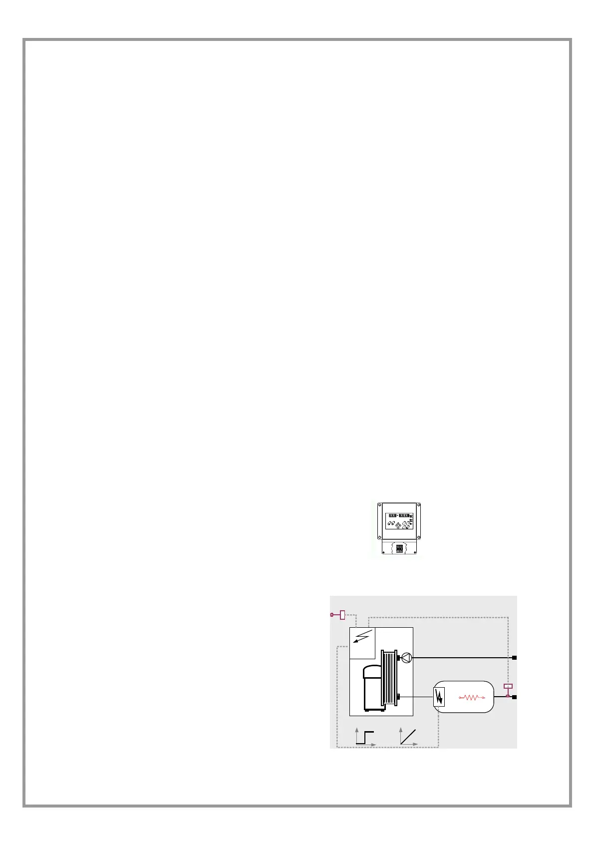
6. ADDITIONAL HEATING ELEMENT
It is possible to control an external element for additional
heating, typically electric heaters.
The control can be:
ON-OFF ( max 1 A )
modulating with signal 0-10 V
(in this case a plug-in expansion module is necessary, an
optional that must be assembled by the customer (refer to the
instructions in the kit) and enabled with the parameter 140=1
The diagram on the side is indicative: check the position of the
water connections on the dimensional drawing of the unit or on
the adhesive labels on the unit itself.
T out1
T ext
O - 10V
ON -OFF