M01W45H6-06
WSAT-SC
75C-180F
- ELECTRICAL CONNECTIONS -
29
HL
gnd
J17
J12
CN1
CN2
DIP1
DIP2
JUMP4
STRIP
gnd
OFF
ON
1234
OFF
ON
12345678
123456
97531
108426
246810
13579
JUMP1
JUMP2
JUMP3
PUMP MODULE
code C5110701
It manages controls and safety devices relative to the circulation pumps
21 20 19 18 17
16
15
14
13
12
DRIVER VCM
1
2
3
4
5
6
7
8
9
10
11
12
ELECTRONIC THERMOSTATIC VALVE EXPANSION MODULE
code C5110802
It manages the electronic thermostatic valve and the respective temperature/pressure
check sensors.
It is fitted on the compressor module.
DRIVER VCM
DRIVER MODULE
code C5110803
Inside there is the management firmware of the electronic thermostatic.
It is fitted on the expansion module.
HL
gnd
8 9 10 11
JUMP4
123 4 5 67
DIP1
DIP2
STRIP
OF
F
O
N
1234
OF
F
O
N
12345678
JUMP1
JUMP2
JUMP3
13579
24810 6
CN2
CN1
161412108642
151311
97531
J22
J15
gnd
RECOVERY MODULE
code C5110679
It manages the electrovalves and the pumps relative to the recovery circuit
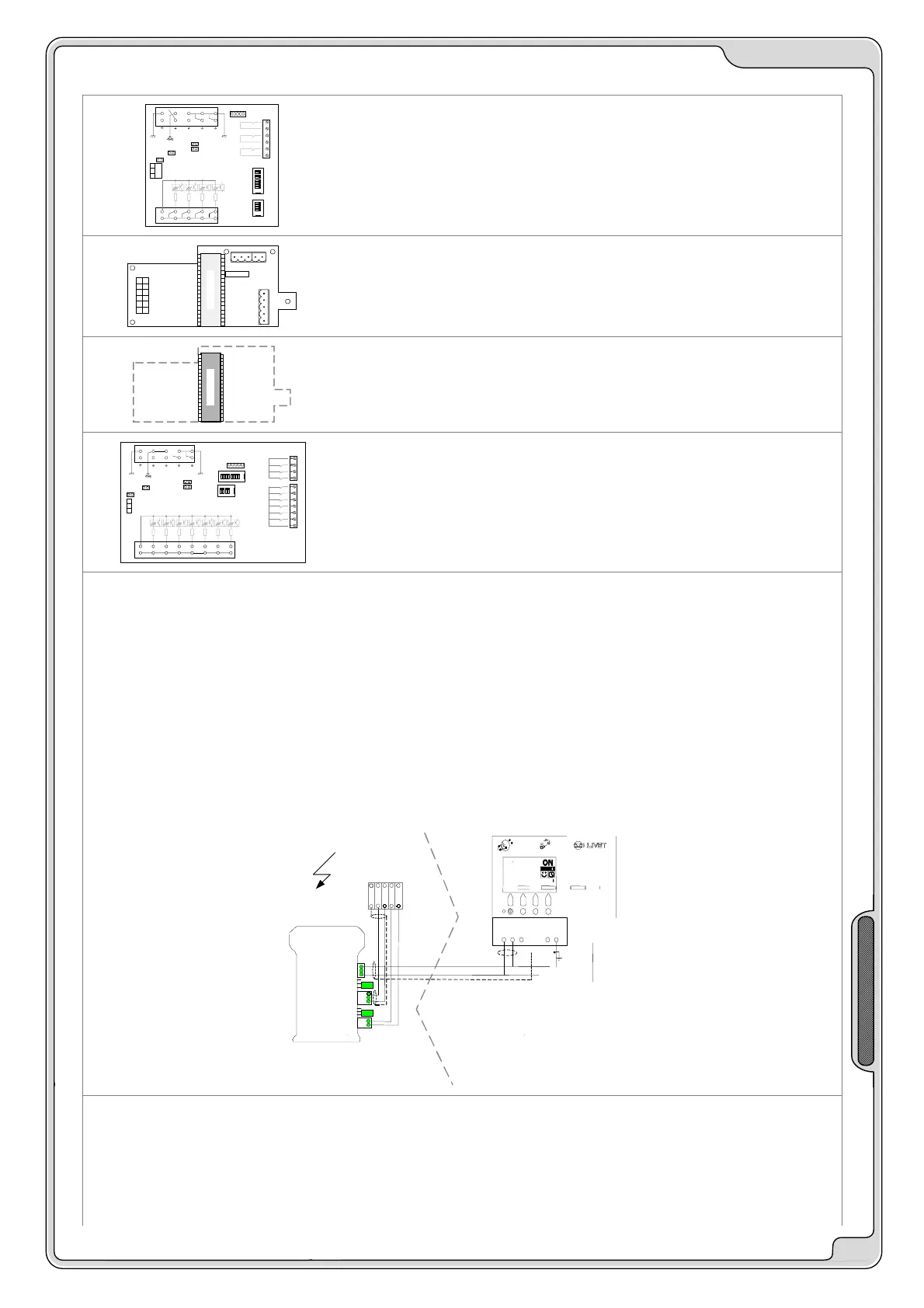
REMOTE TERMINAL
cod PE1W0005
The remote keyboard has the same functions of the keyboard on board of the machine.
The connection of the remote keyboard to the system on board of the machine is carried out, using the “CAN to CAN”
converter, which must be placed in the electric board of the machine
The REMOTE KEYBOARD must be configured with the software address = 27 (only an authorised service centre can
perform this operation).
If the unit is managed by timetables, they must be activated only on one of the two keyboards of the machine, better if
the remote keyboard.
CONNECTIONS: refer to the electric diagram and to the SIGNAL/DATA LINES paragraph.
MODBUS - CONVERTER CAN to MODBUS via RS 485
cod PE1W0003 / 6
Interfacing via RS 485 is performed using a converter for each unit.
The converter must be mounted on the electric board of the unit and connected, following the electric diagram attached
to the unit.
CONNECTIONS: refer to the electric diagram and to the SIGNAL/DATA LINES paragraph.
230/1/5
0
1
2
V
A
C
XC
1
2
1
2
A
H
QE unit 1
G
N
D
C5110675
L
S
H
I
L
D
H
230/1/50
2 X 0.34 mm2
+ sch
CAN to CAN
Can 0
Can 1
 Loading...