Z4II & Z8II Installation and User Manual v1.08
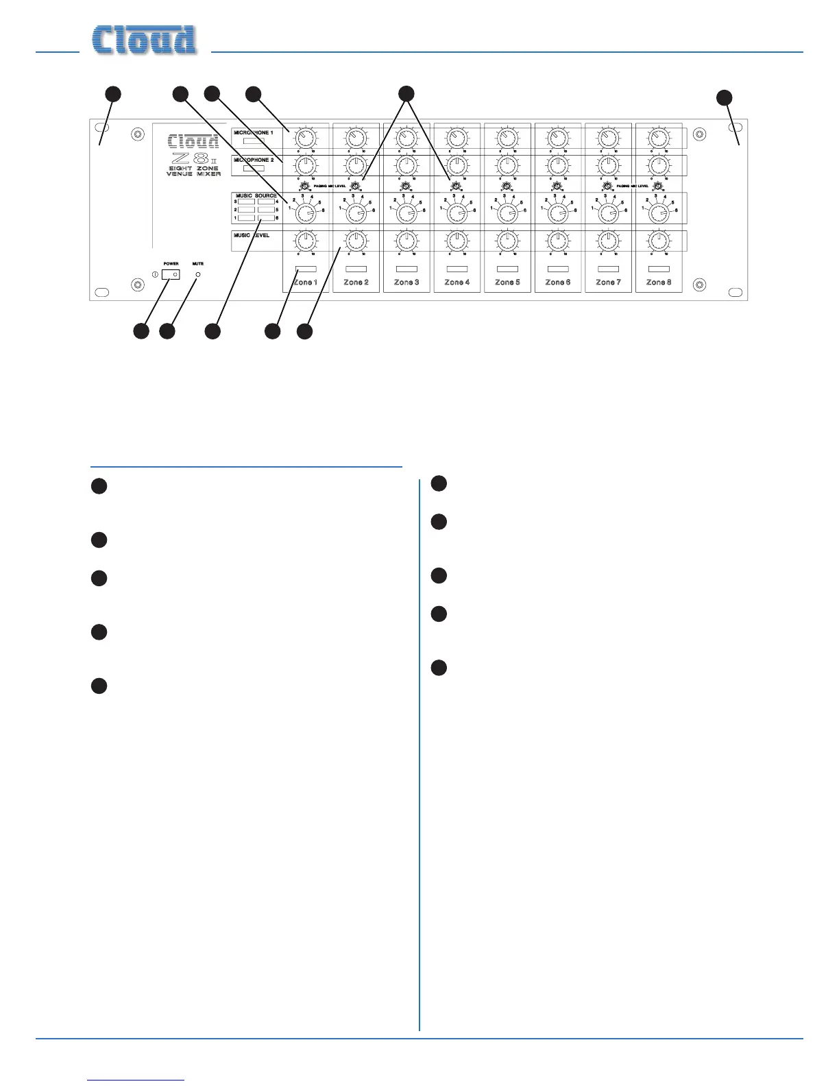
POWER – latching push-button switch with integral
green LED
MUTE – red LED which illuminates when an external
Music Mute command is applied (i.e., from re control
panel, etc.) See page 15 (Music Mute)
Zone idents – a space is provided below each zone’s
controls for printed labels identifying the zone by name
Source idents – a space is provided beside Zone 1’s
source select control for printed labels identifying each
music source by name
Rack mounting ears – the unit may be rack-mounted
in a standard 19” equipment rack. It requires 3U of rack
height. See page 10 (Hardware considerations)
Front Panel Description
MUSIC SOURCE – 6-way rotary switch selecting
which Line Input (1 to 6) will be the music source for
each zone. See page 16 (Local/remote control)
MUSIC LEVEL – adjusts the music level in each
zone. See page 16 (Music Gain & Level)
MICROPHONE 1 – adjusts the level of the
microphone connected at Mic 1 input in each zone. See
page 16 (Microphone Inputs Gain & Level)
MICROPHONE 2 – adjusts the level of the
microphone connected at Mic 2 input in each zone. See
page 16 (Microphone Inputs Gain & Level)
PAGING MIC LEVEL – adjusts the level of the
microphone connected at the Paging Mic input in each
zone. This is a preset control and is intended to be set
on installation and not readjusted by the user. See page
17 (Paging Mic Gain & EQ)
Note - The front panel of the Z8II is shown above.
The Z4II’s is identical, except that it only has controls for zones 1 - 4.
g.8: Z8II Front Panel