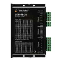
The Cloudray 3DM580S is a digital step servo drive designed for industrial applications, offering enhanced performance over traditional analog stepper drives. It is built on a 32-bit DSP platform developed by TI and incorporates micro-stepping technology and a PID current control algorithm. This design results in low noise, low vibration, low heating, and high-speed, high-torque output, making it suitable for a wide range of stepper motors. The 3DM580S also features S-shape acceleration/deceleration for pulse trains and can trigger motor start-stop operations using normal switching values.
Function Description:
The 3DM580S drive operates in a constant current control mode, converting input power into a PWM chopping wave to deliver voltage to the motor. This process means the input power significantly influences the drive's performance. The drive supports various pulse modes, including Direction & Pulse, CW/CCW double pulse, and A/B orthogonal pulse. It also includes a 2MHz digital signal filter for pulse filtering and automatically halves the current when the motor stops running, reducing heat generation.
A key feature is its resonance suppression, which automatically calculates resonance points and inhibits intermediate frequency (IF) vibration. The drive also includes parameter adaptation, automatically detecting motor parameters during initialization to optimize control performance.
The ENA (enable/disable) port controls the motor's state. When the internal optocoupler is off, the drive supplies current to the motor. When it's on, the drive cuts off current to each motor phase, placing the motor in a free state where it won't respond to stepper pulses. This port can also be used to restart the drive after a fault, provided the fault is cleared and a trailing edge signal is input to the ENA terminal. The level logic of the enable signal can be configured as opposite to the default.
Important Technical Specifications:
- Power Supply: 24-50VDC (Input V+ power supply) or AC 20-80V (Input V+ power supply). The manual explicitly warns against connecting to 220VAC mains and emphasizes correct input power polarity.
- Output Current: Up to 5.6 amps (peak value).
- Current Control: PID current control algorithm.
- Micro-stepping Settings: 16 options configurable via DIP switches.
- Speed Range: Up to 3000rpm, depending on the motor.
- Resonance Suppression: Automatic calculation and inhibition of IF vibration.
- Parameter Adaption: Automatic motor parameter detection and control optimization during initialization.
- Pulse Mode: Direction & pulse, CW/CCW double pulse, A/B orthogonal pulse.
- Pulse Filtering: 2MHz digital signal filter.
- Neutral Current: Automatically halved when the motor stops.
- Vibration Resistance: 0.5G (4.9m/s²) Max.
- Operating Temperature/Humidity: 0°C ~ 45°C / 90% RH or less (no condensation).
- Storage and Transportation Temperature: -10°C ~ 70°C.
- Cooling: Natural cooling / away from the heat source.
- Waterproof Grade: IP54.
Usage Features:
- Motor Compatibility: Designed for low resistance and low inductance hybrid stepper motors, commonly 3-phase with 3 or 6 leads.
- Control Signal Interface: Standard DM series drives use a switch interface. Compatible with pulse signal generating devices such as PLCs, MCUs, control cards, and controllers.
- Pulse Level Compatibility: Supports 3.3V-24V pulse levels without requiring external resistors.
- Power Supply Selection: Higher input voltage can increase motor torque at high speeds, while lower voltage can reduce motor heating for low-speed applications.
- Acceleration/Deceleration: Built-in S-type acceleration and deceleration. The motor accelerates to the set speed when the switch is closed and decelerates to a stop when the switch is off.
- Pulse Filtering Function: Can be enabled to smoothen input pulse commands, resulting in softer motor acceleration and deceleration. The default filtering time is 6.4ms, configurable up to 25.6ms via software.
- Motor Direction Selection: DIP SW5 controls the initial running direction (clockwise or counterclockwise) based on the initial pulse.
- Control Mode Selection: DIP SW8 allows selection between closed-loop and open-loop control modes.
- DIP Switch Configuration: DIP switches SW1-SW4 are used to set the output current, SW6-SW8 for pulse per revolution settings, SW5 for motor direction, SW6 for pulse filtering, SW7 for pulse mode, and SW8 for open/closed loop selection.
Maintenance Features:
- LED Status Indication: Provides visual feedback on the drive's operational status:
- Green indicator on for long time: Drive not enabled.
- Green indicator flickering: Drive working normally.
- One green, one red indicator: Drive overcurrent.
- One green, two red indicators: Drive input power overvoltage.
- One green, three red indicators: Internal voltage of the drive is wrong.
- One green, four red indicators: Tracking error exceeds limits.
- One green, five red indicators: Encoder phase error.
- Troubleshooting Guide: The manual includes a comprehensive troubleshooting section linking common phenomena (e.g., motor not working, incorrect steering, alarm indicator on) to possible causes and solutions. Solutions include checking power supply, adjusting micro-stepping, clearing alarms, checking connections, adjusting DIP switches, and verifying pulse signals.
- Warranty: An 18-month warranty period is provided from the date of delivery, covering free maintenance services. Exclusions include improper connection (e.g., reversed power polarity, hot-plugging motor connections), operation outside electrical/environmental requirements, and unauthorized internal modifications.
- Maintenance Process: To initiate maintenance, customers must contact customer service for rework permission and include a written document detailing the drive failure, contact information, and mailing methods with the returned goods.