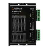
3DM580S USER MANUAL
www.cloudraymotor.com
than the motor’s.
The effects of regeneration voltage:
When the stepper motor is working, it also keeps the characteristics of the generator. At deceleration, the
kinetic energy accumulated by the load is converted into electric energy, which will be superimposed on the
drive circuit and the input power. In application, attention should be paid to the setting of acceleration and
deceleration time to prevent the protection of the drive or power supply.
When the drive is powered off, similarly, the drive LED indicator will be on if the load is increased to allow the
motor to move
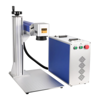
3.3 Motor connection
The matching motor of the 3DM580S-IO drive is the low resistance and low inductance hybrid stepper motor.
The common 3-phase stepper motor’s lead number are 3 and 6.
3.4 Control signal connection
3.4.1 IN Port: connection for pulse command
The signal interface of standard DM series drive is switch.
The upper controller can be the pulse signal generating device, such as PLC, MCU, control card and controller.
The pulse level that R86 drive can be used: 3.3V-24V (no need to connect resistor)
Pulse&Direction
(
PUL + DIR
)