Do you have a question about the Club Car Electric Precedent 2008 and is the answer not in the manual?
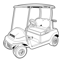
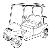
| Model Year | 2008 |
|---|---|
| Model | Precedent |
| Power Source | Electric |
| Seating Capacity | 2 |
| Battery Type | Lead-acid |
| Batteries | 6 x 8V |
| Overall Length | 91.5 inches |
| Ground Clearance | 4.5 inches |
| Payload Capacity | 800 lbs |
| Frame Material | Aluminum |
| Brake Type | Mechanical drum |
| Type | Electric |
| Top Speed | 12-15 mph |
| Charger | 48V Charger |
| Overall Height (with canopy) | 68.5 inches |
| Wheelbase | 65.5 inches |
| Tire Size | 18 x 8.5-8 |
| Suspension | Leaf Spring |
General safety statements to be heeded when operating, repairing, or servicing the vehicle.
General warnings and guidelines for storing the vehicle, including battery preparation.
Provides instructions and precautions for cleaning the vehicle's exterior and interior components.
Details procedures for repairing minor impact damage, stress lines, and scratches on the body panels.
Covers procedures related to the front body assembly of the vehicle.
Details components and procedures specific to the rear body of two-passenger vehicles.
Details components and procedures specific to the rear body of four-passenger vehicles.
Procedures for installing and removing the canopy for two-passenger models.
Procedures for installing and removing the canopy for four-passenger models.
Information regarding the accelerator and brake pedal assembly.
Details about the Motor Controller Output Regulator (MCOR) and its function.
Detailed steps for removing brake shoes, including safety warnings and notes.
Procedures and precautions for cleaning brake assembly components, including lubrication.
Step-by-step guide for installing brake shoes, including proper orientation and adjustment.
Instructions for adjusting brake cable equalizer tension for proper brake performance.
Procedures for removing and installing the brake cluster assembly and related parts.
Steps for removing and installing brake cables, noting design changes and component usage.
Procedures for the removal, disassembly, assembly, and installation of the rack and pinion system.
Details on lubrication and wheel alignment, including camber and toe-in adjustments.
Procedures for inspecting, removing, and installing front wheel bearings and hubs.
Instructions for removing and installing vehicle wheels.
Procedures for removing, repairing, and installing vehicle tires.
Procedures for removing, inspecting, and installing shock absorbers.
Steps for removing and installing leaf springs on two-passenger vehicles.
Steps for removing and installing leaf springs on four-passenger vehicles.
Outlines regular service intervals for owner and technician, detailing tasks and referenced sections.
Details lubrication points, intervals, and recommended lubricants for various vehicle components.
Recommends using the IQDM handset for troubleshooting IQ System vehicles, including safety warnings.
A guide for identifying symptoms, causes, and corrective actions for IQ System issues using IQDM.
Recommends using the IQDM handset for troubleshooting Excel System vehicles, including safety warnings.
A guide for identifying symptoms, causes, and corrective actions for Excel System issues using IQDM.
Instructions on how to connect the IQDM handset to the vehicle's IQDM port.
Explains how to navigate the handset menus using navigation and value change buttons.
Explains the monitor menu for viewing real-time parameters to aid in speed controller troubleshooting.
Describes the faults menu, which displays recorded faults from the speed controller.
Explains the functions menu for transferring settings between the speed controller and the handset.
Instructions for connecting the IQDM-P handset to the Excel System vehicle's IQDM port.
Explains how to navigate the handset menus for Excel System vehicles.
Explains the monitor menu for viewing real-time parameters for Excel System speed controller troubleshooting.
Describes the faults menu, which displays faults detected by the Excel System speed controller.
Explains the functions menu for transferring settings between the Excel System speed controller and the handset.
Procedures for testing, removing, and installing the key switch.
Procedures for testing, removing, and installing the Forward/Reverse rocker switch.
Procedures for testing and removing the MCOR component.
Procedures for removing and installing the electronics module for Style A battery configurations.
Procedures for removing and installing the electronics module for Style B and C battery configurations.
Procedures for testing, removing, and installing the speed controller for Style A configurations.
Procedures for testing, removing, and installing the speed controller for Style B and C configurations.
Procedures for testing, removing, and installing the Onboard Computer for Style A configurations.
Procedures for testing, removing, and installing the Onboard Computer for Style B and C configurations.
Information on testing, inspecting, and removing the charger receptacle.
A flowchart to diagnose battery problems based on test results and symptoms.
Details four progressive tests to diagnose battery problems, starting with basic checks.
Step-by-step instructions for safely replacing vehicle batteries, including safety warnings.
Guidelines for maintaining batteries in good working condition, covering cleaning and connections.
Instructions on checking and maintaining battery electrolyte level, including adding water.
General information about the battery charger and its automatic functions.
Details how to identify the two types of motors used in the vehicles.
Outlines tests for the motor without disassembly using a multimeter or continuity tester.
Step-by-step instructions for removing the motor from the vehicle, including safety precautions.
Procedures for inspecting and testing motor components like armature, field windings, and brushes.
Instructions for checking and filling the transaxle lubricant level.
Procedures for removing and installing axle shafts, seals, and bearings.
Comprehensive guide for disassembling, inspecting, and reassembling the transaxle.
Instructions on how to connect the IQDM-P handset to the vehicle's IQDM port for IQ System.
Explains how to access and use the program menu to adjust speed controller settings.
Instructions for connecting the IQDM-P handset to the Excel System vehicle's IQDM port.
Explains how to access and use the program menu to adjust speed controller settings for Excel System.
