User’s Manual Page ii
USER'S MANUAL
TABLE OF CONTENTS
Contents Page #
1.0 OVERVIEW .................................................................................................................... iii
2.0 FEATURES .................................................................................................................... iii
3.0 SPECIFICATIONS .......................................................................................................... 1
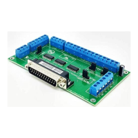
4.0 BOARD DESCRIPTION .................................................................................................. 1
5.0 SPECIFICATIONS .......................................................................................................... 2
5.1 Power Requirements ................................................................................................. 2
6.0 POWER TERMINAL ....................................................................................................... 2
6.2 Enable pin. ................................................................................................................. 3
7.0 LED INDICATOR ............................................................................................................ 3
8.0 CONFIGURATION JUMPERS ........................................................................................ 4
8.1 Using the COM configuration jumper ....................................................................... 4
8.2 Using the Pins 2-9 direction jumper ......................................................................... 4
8.3 Using the Pull-up or Pull-down selection jumper for pins 2-9. ............................... 5
8.4 Using the Pull-up or Pull-down selection jumper for pins 10, 11, 12, 13 and 15. .. 5
9.0 FUNCTIONAL BLOCK DIAGRAMS ............................................................................... 6
9.1 Bidirectional pins simplified block diagram ............................................................ 6
9.2 Dedicated Inputs simplified block diagram ............................................................. 6
10.0 WIRING DIAGRAMS ....................................................................................................... 7
10.1 Connecting Switches or push button. ...................................................................... 7
10.2 Connecting NPN sensors. ......................................................................................... 7
10.3 Connecting in parallel NPN sensors. ....................................................................... 8
10.4 Connecting PNP sensors. ....................................................................................... 10
11.0 DIMENSIONS ................................................................................................................ 11