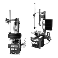
6 • Important: Always read and follow the operating instructions.
9. The mount/demount head should be in contact
with the rim edge. Turn the swing arm adjusting knob
to move the mount/demount head away from the rim
1/8 to 1/4 inch (figure 9).
Figure 9 - Adjust Swing Arm to Position Head Roller
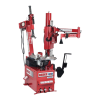
10. Check metal head positioning. Mount/demount
metal head should be positioned with 1/8 to 3/16 inch
clearance between the top of the rim edge and the
bottom of the head, and 1/8 to 1/4 inch clearance
between the rim edge and the head roller. This clear-
ance will be maintained as long as the locking handle
and adjustment knob are not changed. The operator
may swing the arm out of the way and back into place
again without needing to reposition the head (when
changing a like set of wheels) (figure 10).
Figure 10 - Proper (Metal) Mount/Demount Head Position
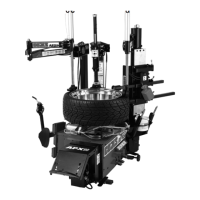
11. Check plastic head positioning. Mount/demount
plastic head should be positioned with 1/16 to 1/8 inch
clearance between the top of the rim edge and the
bottom of the head, and 1/16 to 1/8 inch clearance
between the rim edge
and the inside surface of
the head. This clearance
will be maintained as long
as the locking handle and
adjustment knob are not
changed. The operator
may swing the arm out of
the way and back into
place again without need-
ing to reposition the head
(when changing a like set
of wheels) (figure 11).
Figure 11 - Proper (Plastic) Mount/Demount Head Position
H. The tool clearance may change with
machine use and should be inspected often.
Failure to maintain the proper clearance may
result in damage to the wheel rim and/or tire.
J. Normal table top rotation for demounting is
clockwise. Depress the table top pedal to
rotate this direction. To rotate the table top
counterclockwise, lift the pedal up with your
toe.
K. Table top rotation can be stopped at any
time by removing your foot from the rotation
pedal.
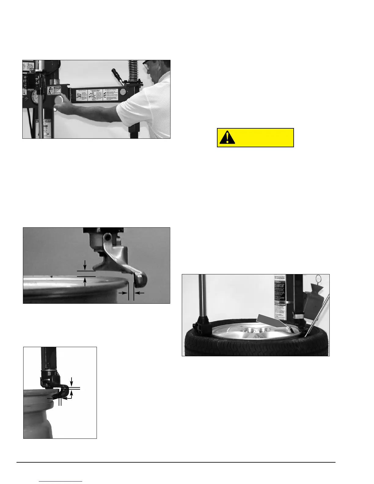
At times during the mounting and
demounting procedure, the bead lifting tool
may encounter resistance and can be
thrown. Keep one hand firmly on the tool to
avoid possible tool disconnect. Use the
reversing feature to back out of jam-ups. A
thrown tool can cause injury.
12. Insert the smooth curved end of the bead lift-
ing tool over the forward end of the demount head and
below the top bead of the tire. Lift the bead up and
over the knob on the Duckhead (figure 12). Also, note
the valve stem position to the Duckhead. Use the Robo
Arm to push down on the tire opposite the Duckhead
to allow the bead to utilize the drop center area of the
rim, this position reduces stresses in the bead and
allows an easier bead lift.
Figure 12 - Insert Bead Lifting Tool
 Loading...