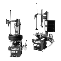
Figure 3 - Position Tire and Bead Loosener Shoe
3. Turn the wheel around and repeat loosening pro-
cedure on the other side of the wheel (figure 4). This
should be the long side of the drop center (figure 2).
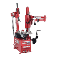
Figure 4 - Position Tire and Bead Loosener Shoe With Wheel
Turned Around
G. It will be easier to outside clamp the wheel
to the table top if the long side of the rim is
loosened last.
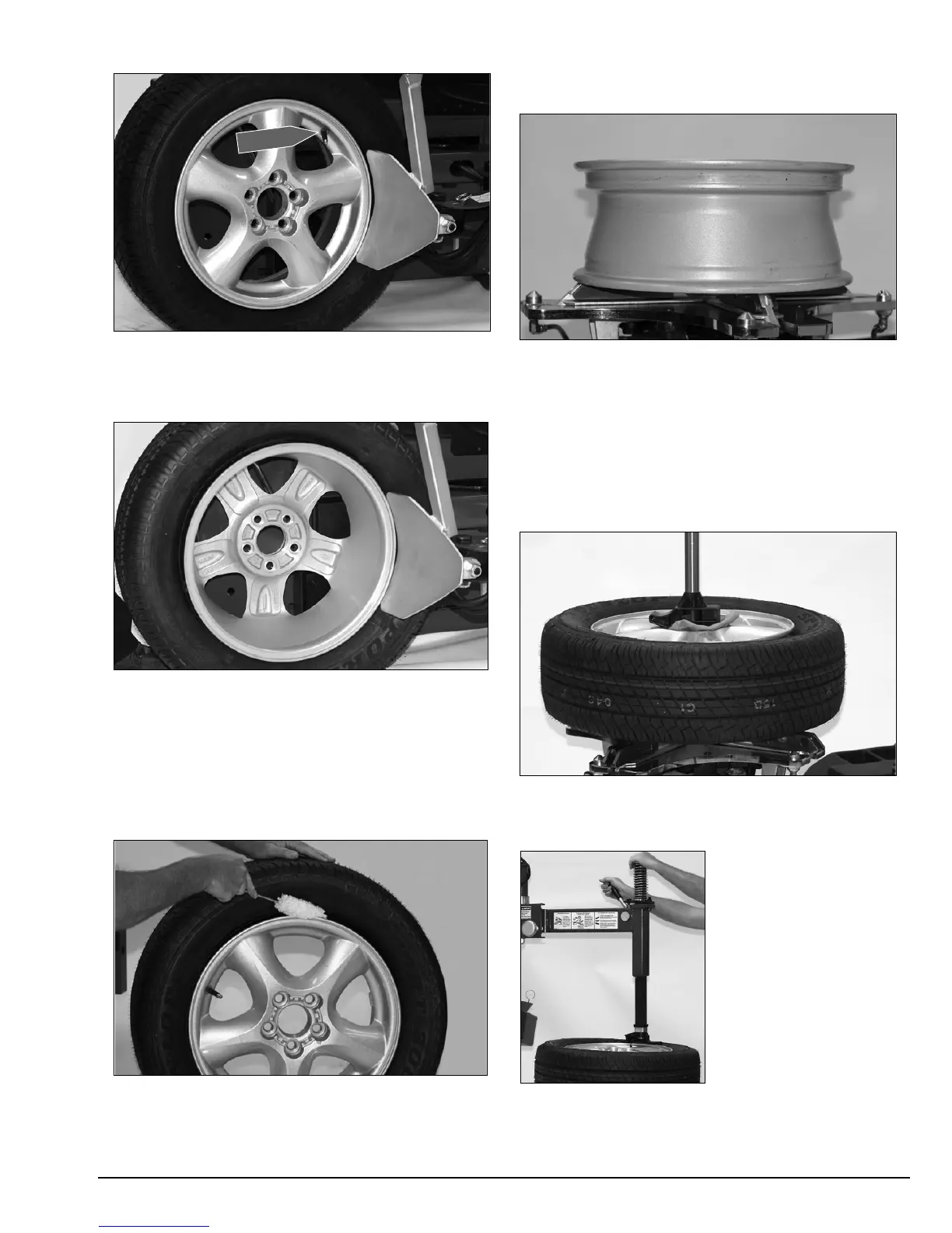
4. Apply tire manufacturer’s approved rubber lubri-
cant liberally to entire circumference of both tire beads
after loosening (figure 5).
Figure 5 - Apply Rubber Lubricant to Tire Beads
5. Determine the mounting side of the wheel. The
mounting side is the narrow side of the drop center.
See figure 2 for more information on the drop center.
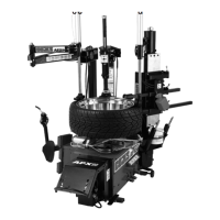
6. Place tire/wheel assembly on table top with
mounting side up (figure 6).
Figure 6 - Place Tire/Wheel Assembly on Table top
7. Use Robo Arm to apply pressure to aid in clamp-
ing rim (figure 7). Use the clamp control pedal to move
the clamps inward (push pedal down) or outward (tog-
gle pedal up). Clamp steel wheels from the inside
(clamps push outward against wheel). Clamp mag and
custom wheels from the outside (clamps push inward
against the outside rim edge). Refer to the
Performance Tires and Wheels section.
Figure 7 - Robo Arm Aids Clamping
8. Move the swing arm into position. Pull the locking
handle forward to release the slide. Push down on the
top of the vertical slide to
move the demount head
into contact with the rim
edge. Push the locking
handle back and lock the
slide into place. As the
slide is locked, the
mount/demount head will
move upward approxi-
mately 1/8-inch from rim
edge (figure 8).
Figure 8 - Position Mount/Demount Tool
Important: Always read and follow the operating instructions. • 5
Valve Stem
 Loading...