Section 1 - General Information
1.7 INSTALLATION KITS AND ACCESSORIES
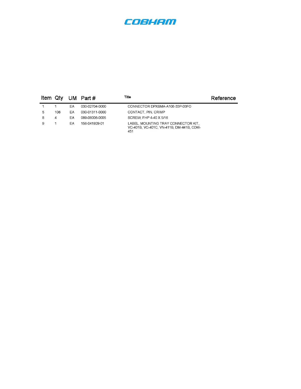
A. CVC-151 CONNECTOR KIT
Installation of a CVC-151 requires a connector kit, P/N 050-02398-0000. The contents of the kit are as
follows:
Table 1-7. Part list, CVC-151 Connector Kit (050-02398-0000, Rev E)
B. SINGLE MOUNTING
When installing a single system, use P/N 400-048124-01 (Single Mounting Tray, Non-Safety Wire
Compatible, 2.5 inch), P/N 071-04047-0000 (Single Mounting Tray, Safety Wire Compatible, 4 inch), or P/N
071-04047-0002 (Single Mounting Tray, Non-Safety Wire Compatible, 4 inch), and one connector kit (050-
02398-0000).
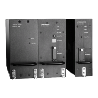
C. DUAL MOUNTING
The CVC-151 racks are designed for stacking two units when required, as shown in Figure 2-4 and 2-5.
Installing a dual mounted configuration requires P/N 400-048124-02 (Dual Mounting Tray, Non-Safety Wire
Compatible, 2.5 inch), P/N 071-04047-0001 (Dual Mounting Tray, Safety Wire Compatible, 4 inch), or P/N
071-04047-0003 (Dual Mounting Tray, Non-Safety Wire Compatible 4 inch), with two connector kits (050-
02398-0000).
D. RETROFIT INSTALLATIONS
The CVC-151 is designed to be installed in the VC-401, 4” mounting rack, P/N 071-04047-0000, without any
aircraft changes. This allows for retrofit into existing installations with minimum effort. An adapter bracket is
available to allow mounting of the CVC-151 into the wider Series III rack. This can be ordered pre-installed
on the unit or as an adapter kit, P/N 149-448014-01.
Note: Retrofit mounting will require a weight and balance change to the aircraft.
1.8 ACCESSORIES REQUIRED BUT NOT SUPPLIED
Headphone, speaker, or audio panel with a 600 ohm impedance that accepts the rated output power.
A VHF Broadband Antenna with a 50 impedance and a maximum of VSWR 3:1.
Microphone or audio panel with a minimum output level of 250 mV.
Coaxial connectors and inter-wiring harness.
The document reference is online, please check the correspondence between the online documentation and the printed version.