D. CVC-151 Harness and Connector Assembly
(1) The installer will supply and fabricate all external cables. The connectors and hardware required are supplied
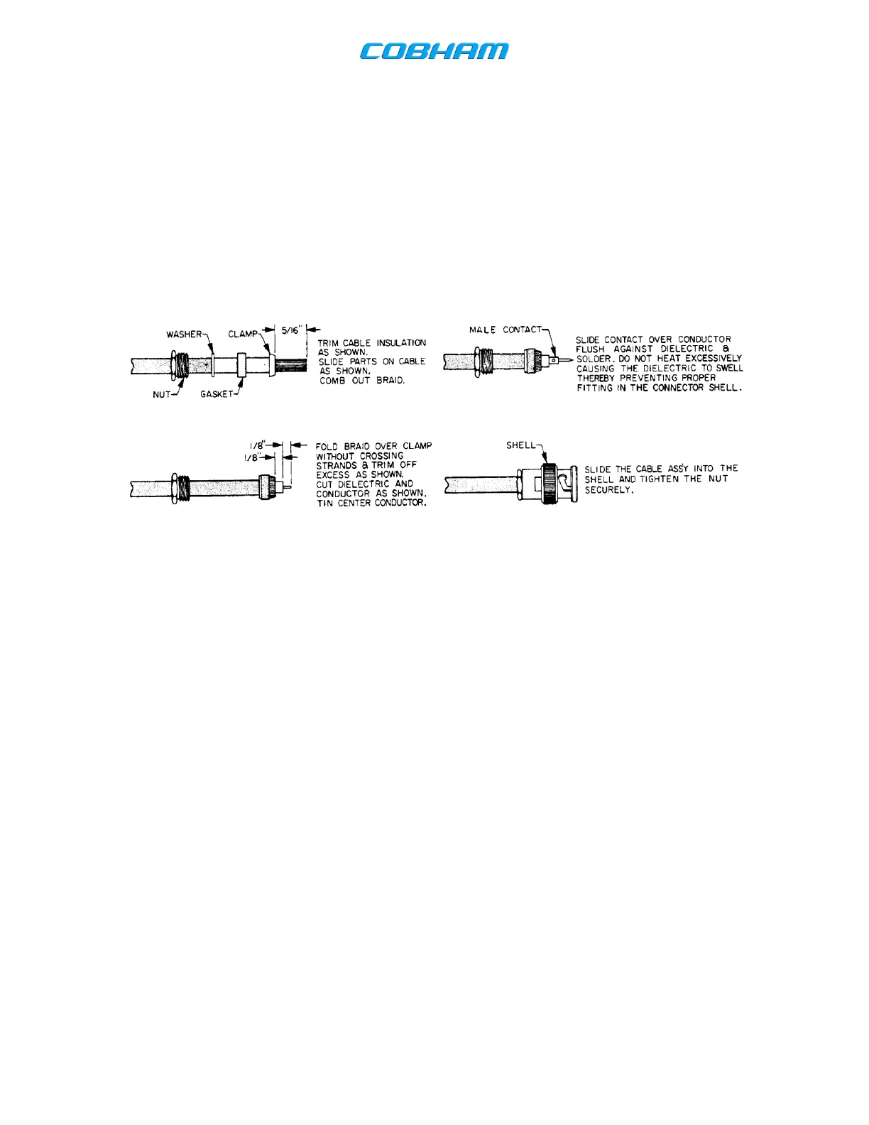
in the Wulfsberg installation kits listed in Section 1. Figure 2-5 illustrates the specific aspects of constructing
the RF connector and the wiring connector housing. Construction details for the antenna end of the coax
cable are dependent on the antenna selected by the installer.
Figure 2-6. RF Cable Fabrication 1
(2) The length and routing of the external cables must be carefully studied and planned before attempting actual
installation. Avoid sharp bends and placing the cables too near the aircraft control cables.
(3) Use only recommended wire sizes and wire type for interconnect. Wire sizes and wire type are listed on the
interconnect diagrams.
(4) Use Figures 2-3 and 2-4 to become familiar with the connectors and pin locations on the plugs for the
fabrication of the external cables.
The document reference is online, please check the correspondence between the online documentation and the printed version.