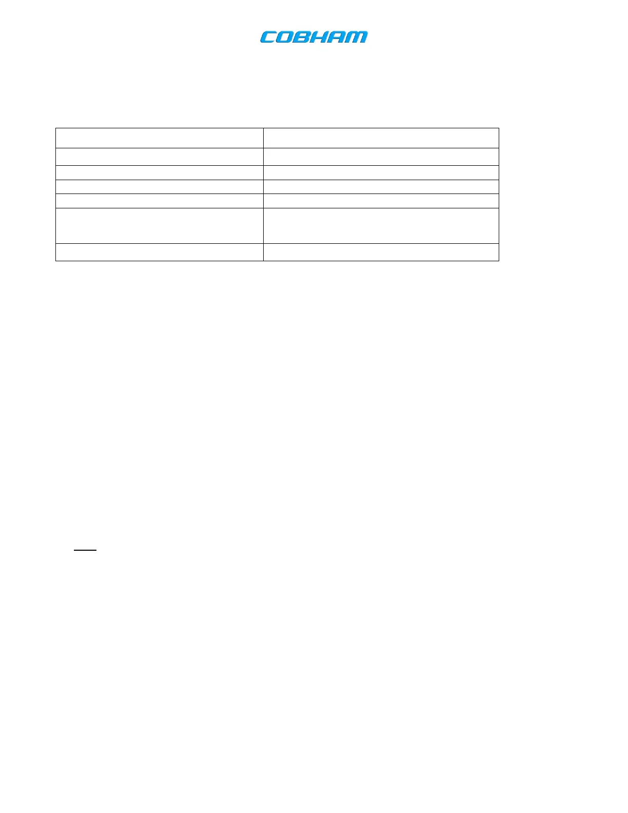
Table 2-2. Strapping Options
P1001-95 and P1001-54 ungrounded
Remote Transfer Function
(Panel or Yoke Mounted)
P1001-56 to one terminal of a momentary SPST
pushbutton switch. Remaining switch terminal is
connected to ground.
Side tone Output through ”COMM AUDIO OUT”
2.4 Post-Installation Check
Check the physical condition of the units, cables, connectors and the areas around the installations. Check to see that all
mounts are secure. Check to see that all cable connections are secure.
A. System Test
The system test will vary as a function of the type of control head used with the CVC-151. The following test is
written for the CVC-152 control head.
(1) Apply ground power to the aircraft. If ground power is not available, testing should be performed with aircraft
engine(s) running.
(2) Apply power to the CVC-151 system. No warm-up period is required. System operation is instantaneous
upon application of power.
(3) Set the CVC-152 COM Control Display function selector to the “ON” position. The CVC-152 displays the last
active (ACT) and standby frequencies of the CVC-151 VHF Communications Transceiver.
(4) Tune the CVC-151 system to the local tower or ground control frequency.
Note: If the system is set up for standby frequency tuning, momentarily depress the frequency transfer
pushbutton so that the desired frequency is displayed in the active (ACT) frequency display.
(5) Key the transmitter of the CVC-151. Each time the push-to-talk button is depressed, the CVC-152 transmit
annunciator (Tx) is displayed. Request a radio check, and release the push-to-talk button. VSWR should be
checked at this time.
The document reference is online, please check the correspondence between the online documentation and the printed version.