Chapter 3: Connecting cables
22 SSA and Alarm Panel (X7 to X14)
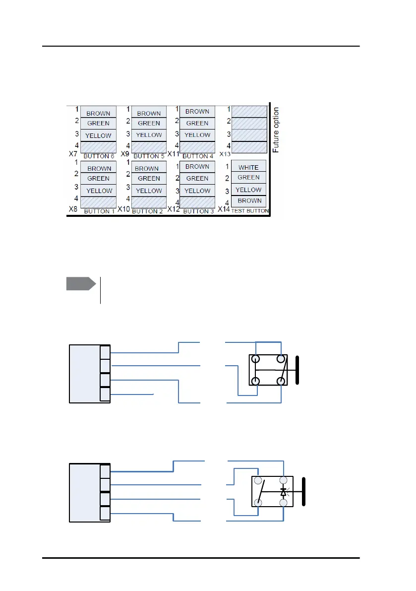
The Terminal Control Unit can connect up to 6 alarm buttons and 1 test
button. The pin-out is shown below.
The following spring-loaded terminals are used for the buttons:
• SSA Alarm buttons: X7, X8, X9, X10, X11 and X12.
• SSA Test button: X14.
Connect the buttons as shown below:
Note
Before inserting the wires into the terminals, make sure there is no
jumper between pin 1 and 2 (Output and Input).
PIN 2 In
PIN 3 GND
PIN 4 3,3V
NONC
SSA
Button 1-6
NO
SSA Test
Button
Green
White
Yellow
Brown
PIN 1 Out 1
2
a
1
2
b
PIN 1 Out
PIN 2 In
PIN 3 GND
PIN 4 3,3V
Green
Brown
3
4
Yellow
Terminal
Block
X14
Terminal
Block
X7-X12