Chapter 3: Connecting cables
SSA and Alarm Panel (X7 to X14) 23
33333
Connecting cables
Note that there may also be a white wire in the cables for the SSA Alarm
buttons. Do not connect the white wire from the red SSA alarm buttons -
only from the Test button.
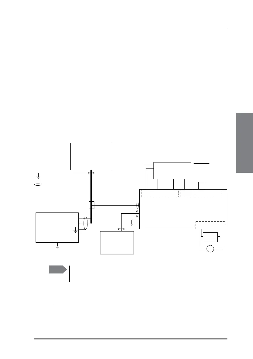
Non-SOLAS Distress systems (SAILOR 6150)
The multi-purpose interface on the Terminal Control Unit can also connect
to Non-SOLAS Alarm Panels e.g. in Non-SOLAS Distress installations. When
a SAILOR 3027D is connected, X8, X10, X12 and X14 are automatically
1
configured as shown in the two following drawings. X13 is not used.
With 1 TT-3042E Non-SOLAS Alarm Panel (Inmarsat C Distress
Alarm Box):
1. See extra information for use with 1 TT-3042E Non-SOLAS Alarm Panel in
the block diagram and the note below it.
6$,/25
7HUPLQDO&RQWURO8QLW
6$,/25
1RQ62/$6
7HUPLQDO
&$1
&$1EXV
LQFOXGLQJ
SRZHU
&$1;
6KLSJURXQGKXOO
3RZHUVXSSO\
'&RXWSXW
6KLHOG
:
:
&
&KDVVLV
&OHDU
EXWWRQ
1RQ62/$6
$ODUP3DQHO
1&
/('
;
;
;
1&
12
12
%X]]HU
9&&
:
&RPSXWHURU
6$,/25
ZLWKHDV\0DLO
/$1
&$1EXVLQFOXGLQJSRZHU
/$1;
*UH\
3LQN
<HOORZ
%URZQ
:KLWH
*UHHQ
&KDVVLV
:
&$1
SRZHU
RQO\
;
,PSRUWDQW,IQR
VHFRQGDODUPSDQHO
LVFRQQHFWHGWR;
\RXPXVWFRQQHFWSLQ
DQGLQ;
Note
Make sure to connect 1 and 2 in X12 if you only have 1 TT-3042E
Non-SOLAS Alarm Panel.