Do you have a question about the COBHAM SAILOR 900 Ka and is the answer not in the manual?
Lists minimum configuration steps for the SAILOR 900 Ka system.
Defines the target audience for the installation and service manual.
Provides a summary of the manual's chapters and appendices.
Specifies the manual's applicability to a particular software version.
Overview of the SAILOR 900 Ka VSAT antenna system.
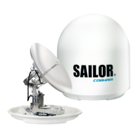
Details about the ADU, its specifications, and protection.
Description of the ACU as the central control unit for the system.
Information on the iDirect X7 modem used in the system.
Lists available part numbers and optional components for the SAILOR 900 Ka system.
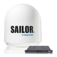
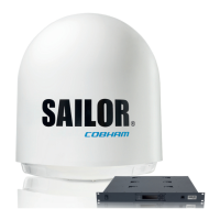
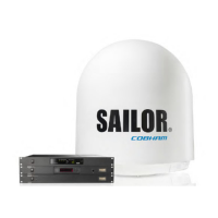
Lists the components included in the SAILOR 900 Ka system package.
Covers essential considerations for preparing the installation site for the ADU.
Step-by-step instructions for installing the Above Deck Unit (ADU).
Instructions for installing the Antenna Control Unit (ACU) in a rack.
Details the procedure for connecting the ADU, ACU, and modem components.
Describes the various interfaces and connectors available on the ACU.
Details the DC power input connector for the ACU.
Describes the N-connector used for the ADU cable.
Explains the Rx Out and Tx In connectors on the ACU.
Details the NMEA 0183 connector for ship's gyro input.
Describes the RS-232 and RS-422 connectors for modem control.
Details the four Ethernet LAN connectors on the ACU.
Discusses the DC power supply options for the ACU.
Provides information on power cable recommendations and source impedance.
Outlines the step-by-step procedure for powering up the system.
Explains how to access and use the system's web interface for configuration.
Details the process for calibrating the antenna system.
Covers overview and dashboard features of the web interface.
Guides on setting up satellite and VSAT modem profiles.
Explains the ACU's keypad and menu structure for system navigation.
Provides a checklist for verifying the antenna installation.
Checklist for verifying ACU, modem, connectors, and wiring.
Checklist for performing a functional test in harbor.
Information on how to obtain technical support and help.
Instructions for updating the system's software.
Explains the meaning of LEDs and status messages for system monitoring.
Provides guidelines and initial checks for troubleshooting system issues.
Lists the components of the SAILOR 900 Ka system.
Presents the technical specifications for the Above Deck Unit (ADU).
Presents the technical specifications for the Antenna Control Unit (ACU).
Explains the necessity of grounding for safety and ESD protection.
Provides recommendations for grounding the ACU and ADU.
Details grounding methods for steel-hulled vessels.
Details grounding methods for aluminum-hulled vessels.
Details grounding methods for fiber glass-hulled vessels.
Instructions for constructing and connecting a separate ground cable.
Discusses how to mitigate RF interference issues.
Provides an overview of system events and their handling.
Lists and explains ADU-specific error codes and events.
Lists and explains ACU-specific error codes and events.
Introduces the command line interface for system configuration.
Details how to establish a Telnet connection to the system.
Lists and describes the available command-line interface commands.
States the CE certification of the SAILOR 900 Ka under the R&TTE directive.
