Do you have a question about the COBHAM Sailor 900 VSAT and is the answer not in the manual?
Details important safety warnings, cautions, and notes to ensure safe operation.
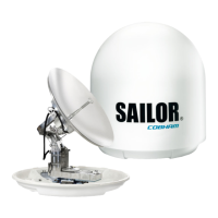
Provides a comprehensive overview of the SAILOR 900 VSAT system, its capabilities, and components.
Lists the key features and functionalities of the SAILOR 900 VSAT system.
Describes the ADU's physical specifications, weight, and operational characteristics.
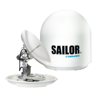
Details the various modules within the ADU, including their function and location.
Explains the interface and communication protocols between the ACU and ADU.
Details the service-friendly features of the ADU, facilitating maintenance.
Describes the ACU as the central unit managing system communication and user interface.
Lists and describes the various interfaces and connectors available on the ACU.
Lists available part numbers for the system components and optional accessories.
Provides instructions for unpacking the system components and checking the contents.
Details the initial inspection process for shipping cartons and system components.
Lists all necessary tools required for the installation process.
Covers essential site preparation steps before installing the ADU.
Provides guidelines for selecting an optimal installation location for the ADU.
Discusses the importance of clear line-of-sight and avoiding obstructions for the ADU.
Explains how to set up blocking zones to prevent transmission in specific areas.
Details the minimum safety distance required due to radiation hazards from the ADU.
Advises on mounting the ADU considering ship motion and its center.
Covers requirements for ADU mast design, including foundation and height.
Specifies the requirements for the ADU mast flange, including thickness and gusset plates.
Discusses potential interference sources and their impact on the system.
Provides guidance on minimum separation distances from radars to avoid interference.
Covers additional precautions related to installation and environmental factors.
Provides step-by-step instructions for installing the Above Deck Unit (ADU).
Details the process of mounting the ADU onto the mast flange.
Provides instructions on how to open and remove the ADU's service hatch.
Lists alternative ADU cable types and their maximum allowed lengths.
Provides instructions for installing the Antenna Control Unit (ACU).
Details the process of mounting the ACU into a 19-inch rack.
Provides guidance on installing the VSAT Modem Unit (VMU).
Offers considerations for mounting the VMU close to the ACU.
Describes the procedure for installing the optional dual-antenna system.
Details the various interfaces and connectors on the ACU, including LEDs and display.
Provides an overview of the ACU's connector panel layout.
Describes the DC input connector, its pin assignment, and power connection.
Details the N-connector used for the ADU cable, specifying its function.
Explains the Rx/Tx connectors for connecting the VMU to the ACU.
Describes the NMEA 0183 connector for gyro/GPS input and its specifications.
Details the RS-232 and RS-422 connectors used for modem control.
Describes the Ethernet LAN connectors (RJ45) for network connectivity.
Covers the interfaces of the VSAT Modem Unit (VMU).
Guides on connecting iDirect iNFINITI series satellite routers to the ACU.
Provides instructions for connecting iDirect Evolution satellite routers to the ACU.
Details how to connect COMTECH 570 L or 625 satellite modems.
Guides on connecting STM Satlink 2900 VSAT modems.
Provides instructions for connecting Gilat SkyEdge II VSAT modems.
Discusses the available options for powering the system, including DC ship supply and AC/DC adapter.
Covers factors affecting power cable selection, such as length and source impedance.
Explains the importance of source impedance in relation to power cable length and system stability.
Details the procedure for measuring the ship's DC power source impedance.
Provides recommendations for selecting and installing power cables, including calculating maximum length.
Guides on connecting the power cable to the ACU.
Outlines the procedure for powering up the system and its initialisation steps.
Details the step-by-step procedure for powering up the ACU and system.
Introduces the built-in web interface for system configuration.
Provides an overview of the web interface, including its menus and topics.
Explains how to establish a connection to the ACU's web interface.
Guides through the process of calibrating the SAILOR 900 VSAT system.
Details how to set up a service profile for system calibration.
Describes procedures for setting vessel heading and performing azimuth/cable calibration.
Provides instructions for performing the line-up procedure for the system.
Explains the principle of fixed TX gain in the SAILOR 900 VSAT system.
Details how to configure the system using the web interface.
Explains the dashboard layout and navigation within the web interface.
Describes the various information fields displayed on the system dashboard.
Explains how the BUC TX output power is displayed and interpreted.
Covers the management of satellite and VSAT modem profiles for system connection.
Details how to add, edit, and delete satellite profiles.
Guides on creating new satellite profiles and editing existing ones.
Explains how to manage VSAT modem profiles, including supported models.
Guides on adding and editing VSAT modem profiles.
Details how to define blocking zones, specifying azimuth and elevation angles.
Provides ACU grounding guidelines for fiberglass hulls.
Details ADU grounding procedures for fiberglass hulls.
| Antenna Type | VSAT |
|---|---|
| Frequency Band | Ku-band |
| Operational Temperature Range | -25°C to +55°C |
| Stabilization | 3-axis |
| Pointing Accuracy | 0.2° RMS |
| Data Rates (receive) | Up to 50 Mbps |
| Weight | 85 kg |
| Polarization | Linear |
| Radome Diameter | 1.3 m |
| Tracking | Automatic |
| Wind Survival | 100 knots |
| Power Supply | 100-240 VAC, 50-60 Hz |
| Compliance | CE, FCC, ETSI |
