Removal and replacement of ADU modules
8-24 Chapter 8: Service & maintenance 98-133966-G1
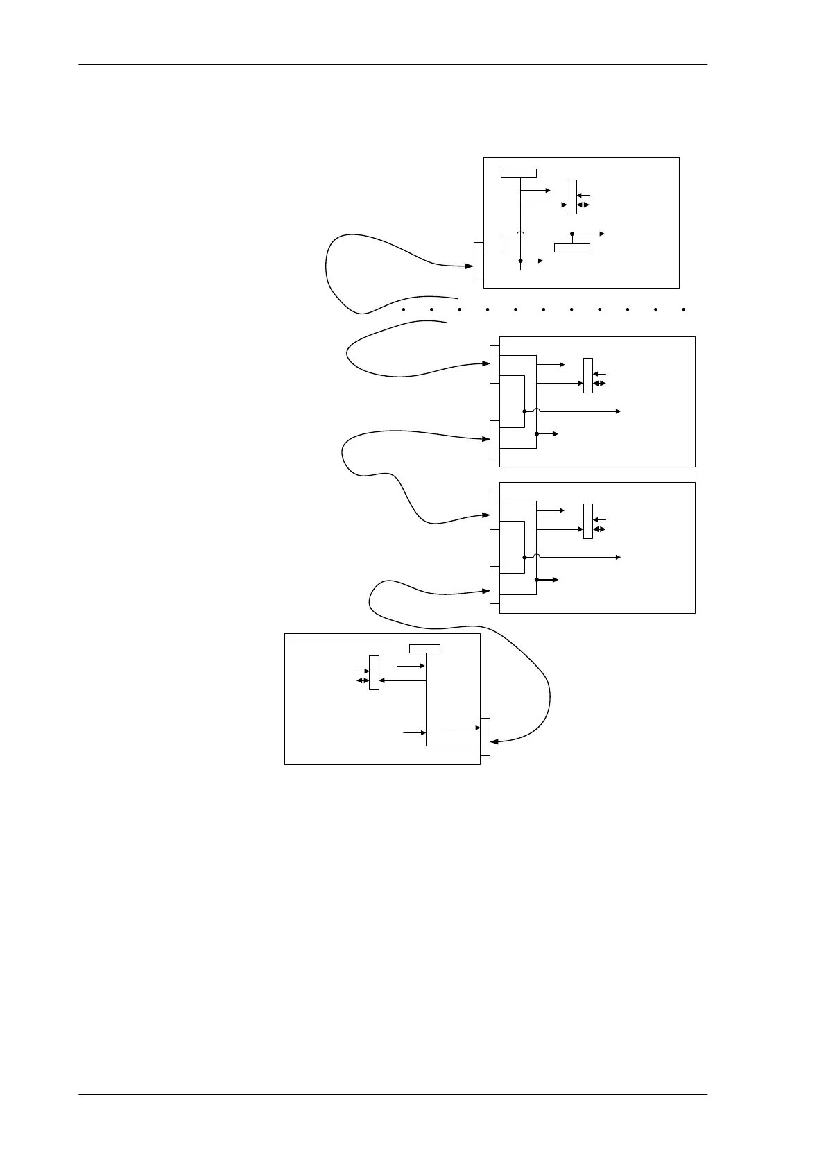
8.5.2.1 S-bus
The S-bus is as a single master/multi slave half-duplex UART link,
mastered by the PCM module (5 Mbit/s).
The S-Bus master and slave modules are - by means of shielded DB9
cables - connected in a chain in the following order; PCM -
DDM(azimuth) - DDM(x-elevation) - DDM(elevation) - ISM - PPM. End
modules contains signal terminations.
Figure 8-22: Block diagram – S-bus
56
6%XV6ODYHQ
$GGU
JQG
'%
WHUPLQDWLRQ
969P
56
6%XV0DVWHU
JQG
'%
WHUPLQDWLRQ
6%XV
$GGUHVVLQJ6FKHPH
969P
WHUPLQDWLRQ
6HULDO$GGU
6HULDO$GGU
56
6%XV6ODYH
$GGU
'%'%
969P
JQG
6HULDO$GGU
56
6%XV6ODYH
$GGU
'%'%
969P
JQG
6HULDO$GGU
SAILOR900TM.book Page 24 Monday, September 16, 2013 11:01 AM
 Loading...