Interfaces of the SAILOR 900 VSAT ACU
98-133966-G1 Chapter 4: Interfaces 4-3
4444
Interfaces
4.1.4 ADU connector
There is just one cable from the ACU to the ADU. This is used to power
the ADU, supply 10 MHz clock, handle all communication between ACU
and ADU, and deliver the VSAT Rx and Tx signals.
4.1.5 Rx/Tx connectors for VMU
Connect the Rx and Tx channels of the VMU to the Rx and Tx
connectors of the ACU with the 2 supplied Rx/Tx cables (75 Ohm coax,
F-F, 1 m).
For step-by-step guidelines how to set up the VSAT modem see VMU
settings on page C-1.
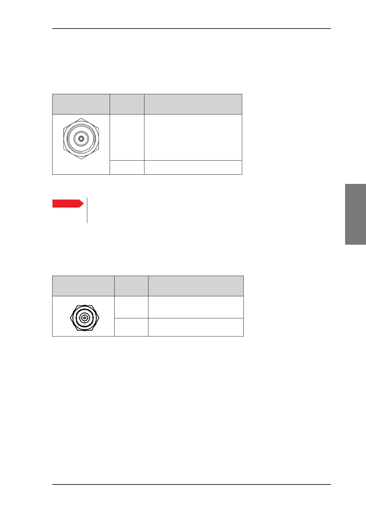
Outline
(on the ACU)
Conductor Pin function
Inner DC to ADU
10 MHz clock to ADU
ACU to ADU internal
communication
VSAT Rx/Tx
Outer GND (Shield)
Table 4-2: N connector, outline and pin assignment
Important
Do not use TNC connectors on the ADU antenna cable
or on pigtails. TNC connectors cannot carry the DC
current for operating the ADU.
Outline
(on the ACU)
Pin
number
Pin function
1 Inner conductor:
10 MHz clock, VSAT Rx/Tx
2 Outer conductor: GND (Shield)
Table 4-3: F connector, Rx and Tx, outline and pin assignment
SAILOR900TM.book Page 3 Monday, September 16, 2013 11:01 AM
 Loading...