Installation of the ACU
3-24 Chapter 3: Installation 98-133966-G1
3.4 Installation of the ACU
The following sections describe the installation and grounding of the
ACU.
3.4.1 Installing the ACU
A cable relief bracket is already mounted when receiving the ACU. The
cable relief is a simple system to secure cables with cable strips. It offers
a number of holders to which you can secure the cables from the ACU.
To install the 19” rack version of the ACU, do as follows:
1. Slide the ACU into a 1U space in a 19” rack.
2. Mount the screws in each side through the holes in the front and
fasten the screws to the rack. Make sure that the unit is mounted
securely according to the requirements for your 19” rack.
3. Connect all cables. See Interfaces of the SAILOR 900 VSAT ACU on
page 4-1 for a description of the ACU connectors.
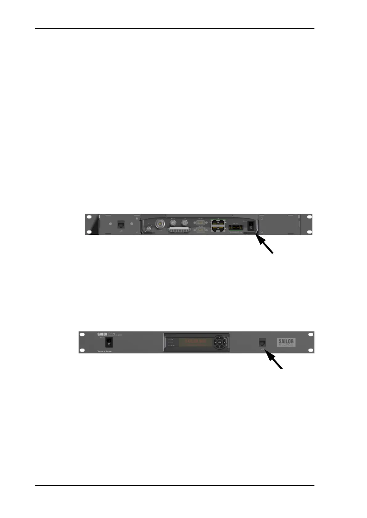
4. Set the On/Off switch at the back of the ACU to On. Then you can
use the On/Off switch at the front panel.
For a description of the connectors see ACU connector panel —
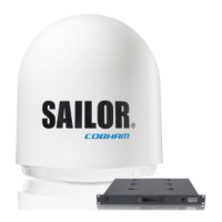
overview on page 4-1. The ACU has additionally a LAN connector at the
front for accessing the service port from the ACU front panel.
For information on wiring 24 VDC power see DC Input connector on
page 4-2.
For information about power supply and power requirements see
Connecting power on page 5-1.
Figure 3-22: ACU, On/off switch at the back
Set to ON
Figure 3-23: ACU, LAN connector at the front: Service port
Service port
SAILOR900TM.book Page 24 Monday, September 16, 2013 11:01 AM



 To Next Page