Interfaces of the SAILOR 900 VSAT ACU
4-6 Chapter 4: Interfaces 98-133966-G1
4.1.8 LAN1, LAN2, LAN3 and LAN4
connectors
Four Ethernet connectors (type RJ45) for PC/lap tops, routers, wireless
access points. The maximum cable length per connection is 100 m.
Depending on the VMU connected, a LAN connector may be used for
modem control.
For information how to configure the LAN network see Configuring the
LAN network on page 6-28.
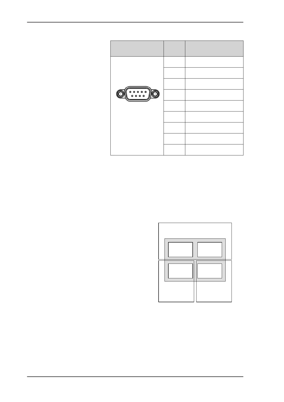
Outline (on the ACU)
Pin
number
Pin function
1 Ground
2 Line A RXD (+)
3 Line B TXD (-)
4 Ground
5 Ground
6 Not connected
7 Line A RXD (-)
8 Line B TXD (+)
9 Not connected
Table 4-6: RS-422 connector, male, outline and pin assignment
Figure 4-5: LAN1 —LAN4 connectors
1 5
6 9
3RUW 3RUW
3RUW 3RUW
6HUYLFHSRUW
1HWZRUN
96$7PRGHPFRQWURO
1HWZRUN
1HWZRUN
SAILOR900TM.book Page 6 Monday, September 16, 2013 11:01 AM



 To Next Page