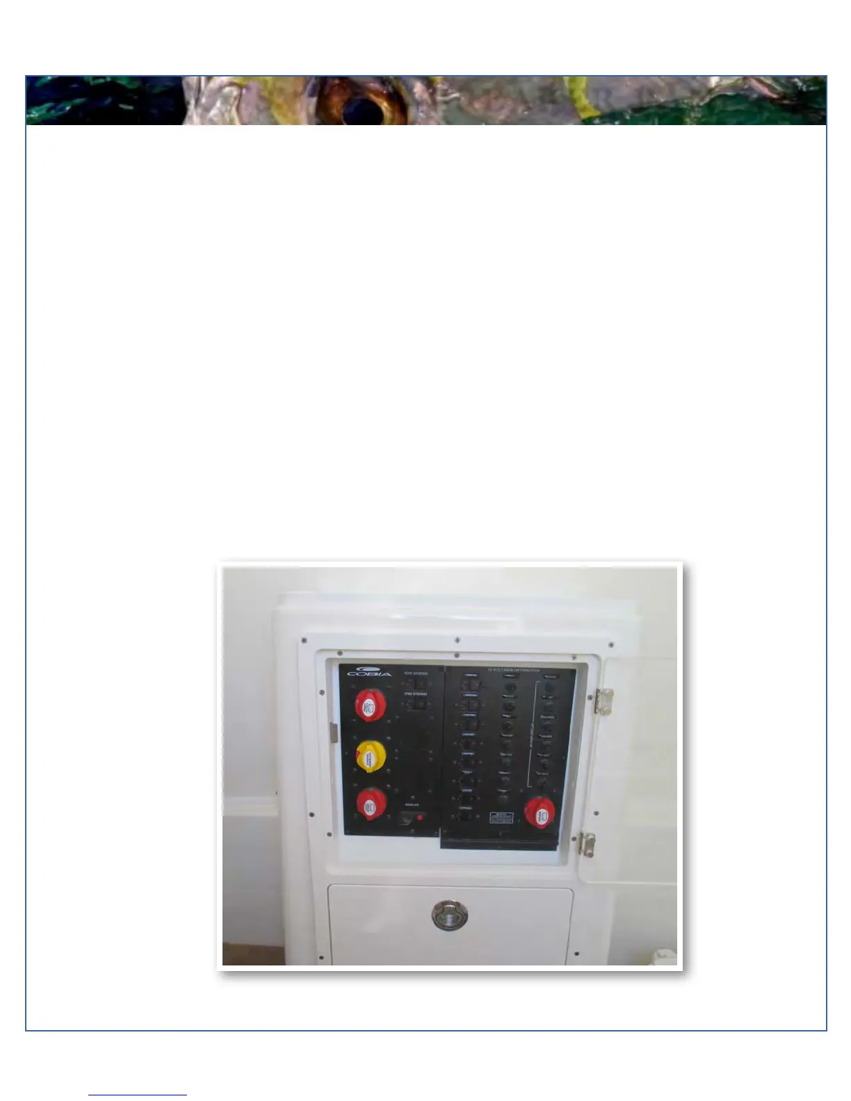
Battery Switch and Breaker Panel
The battery switch assembly and main breaker panel is located in the console in the compartment directly across from the
console access door. This houses the controls for all the batteries and the breakers for all of the boat’s systems. Please
refer to page 36 (twins) or page 37 (trips) for a diagram of the front side of the panel. The "House" battery switch powers all
the systems shown on the labeled breakers on the 12 V Distribution Panel. The switch is turned on by turning the knob a
quarter turn to the right. A red indicator light on the switch illuminates if the switch and its associated systems are receiving
power. If the switch does not illuminate, the house battery is likely either dead or there is a loose connection.
The top unlabeled breakers on the left side of the 12 V Distribution Panel are typically left open to accommodate adding
accessories. All breakers are clearly labeled for their systems and have the proper amperage size. Those labeled "ACC" are
left open for adding additional accessories.
The windlass system is tied to the "House" battery switch and utilizes a reset breaker that is located just to the right of the
starboard engine battery switch. When the breaker has been popped or is in the open position, as shown in the diagram, the
circuit is interrupted and the system is not receiving power. To close the circuit, simply push the end of the gate back into the
breaker until it catches. The windlass should now be operational. The circuit can be opened again by pushing down on the
red button on the breaker.
Each engine has it's own designated battery and battery switch. These switches are located on the left side of the panel
and labeled for the engine they control and also provide power to the steering system. In order for an engine to receive
power, it's switch must be in the "On" position, which is indicated as shown in the diagram on page 31. In the event that
there is not enough power to crank the engine from it's designated battery, turning the battery switch labeled “emergency
parallel” to the "on" position will allow you to pull power from the engine batteries simultaneously. If this is required to start
the engine, it is recommended to change this switch back to the "off" position once the engine is running so that the engine's
alternator can recharge the primary battery.