R
R
GB
GB
VOLUMETRIC ULTRASONIC SENSOR (Ref. B)VOLUMETRIC ULTRASONIC SENSOR (Ref. B)
VOLUMETRIC ULTRASONIC SENSOR (Ref. B)VOLUMETRIC ULTRASONIC SENSOR (Ref. B)
VOLUMETRIC ULTRASONIC SENSOR (Ref. B)
The transducers can be installed on the windscreen or rear window pillars. The best
place is just above the surface of the dashboard.
Wherever they are installed, make sure that the transducers do not interfere with any
other parts.
It is of fundamental importance to correctly position the transducers so that they are
able to offer a full degree of volumetric protection: direct the transducers towards the
rear window so that they approximately converge towards the center of it. Fix them
with the supplied screws. Make sure that the transducers are not obstructed by any
other object (plugs, covers, upholstery).
This unit incorporates an ultrasonic sensor that does not need to be adjusted. ItThis unit incorporates an ultrasonic sensor that does not need to be adjusted. It
This unit incorporates an ultrasonic sensor that does not need to be adjusted. ItThis unit incorporates an ultrasonic sensor that does not need to be adjusted. It
This unit incorporates an ultrasonic sensor that does not need to be adjusted. It
is alris alr
is alris alr
is alr
eady pready pr
eady pready pr
eady pr
esetted indipendently by the difesetted indipendently by the dif
esetted indipendently by the difesetted indipendently by the dif
esetted indipendently by the dif
ferfer
ferfer
fer
ent vehicle interent vehicle inter
ent vehicle interent vehicle inter
ent vehicle inter
nal space.nal space.
nal space.nal space.
nal space.
GLASS BREAK SENSOR (ref. A)GLASS BREAK SENSOR (ref. A)
GLASS BREAK SENSOR (ref. A)GLASS BREAK SENSOR (ref. A)
GLASS BREAK SENSOR (ref. A)
Remember to fix the relative microphone in a central position of the vehicle. The best
place is on the dashboard, pointing towards the rear window. This position achieves
uniform sensitivity.
BONNET BUTTONBONNET BUTTON
BONNET BUTTONBONNET BUTTON
BONNET BUTTON
Use the material supplied in the kit. After it has been installed, make sure that the
button is pressed by the bonnet to the extent of at least 5 mm. Make sure that the
button is unable to press against the soundproofing panels or on the external bodywork
since these materials could become deformed in time.
Cover the button with a film of grease to protect it from rust.
ANTENNAANTENNA
ANTENNAANTENNA
ANTENNA
The antenna is of fundamental importance for operation of the radio control system.
Comply with the following instructions:
The wire must not be cut, wound, connected to other wires or to the bodywork.
Keep the antenna at least 20 mm far from the car body and other metallic parts.
ELECTRICAL CONNECTIONSELECTRICAL CONNECTIONS
ELECTRICAL CONNECTIONSELECTRICAL CONNECTIONS
ELECTRICAL CONNECTIONS
We raccomand you to pay attention while joining together two or more wires. It is
inadvisable to make “quick junctions” that fail to ensure good quality connections.
Remember to position the alarm wires so that they are routed along with the original
harness of the vehicle and to attach them to this with the relative clamps.
Refer to the enclosed wiring diagrams when making the electrical connections, bearing
the following instructions in mind.
• the ground must be shunted from an original ground point of the vehicle or connected
straight to the negative pole of the battery.
• the positive wires of the alarm unit must be connected to a positive of the fuse box
(with the voltage drop sensor activated the alarm unit power supply must be connected
to the entry light wire feed).
• the engine immobiliser function must be obtained by interrupting the fuel pump relay
or pump control circuits. It is essential to block the fuel pump in vehicles with catalytic
silencers. The internal relay and the engine immobiliser wires withstand the maximum
current rating indicated in the wiring diagrams. Before connecting the GREEN wires,
remember to measure the current in the point selected for the connection.
The interrupted wire can be either positive or negative
•
The unit is alrThe unit is alr
The unit is alrThe unit is alr
The unit is alr
eady equipped with inteready equipped with inter
eady equipped with inteready equipped with inter
eady equipped with inter
nal solid state electrnal solid state electr
nal solid state electrnal solid state electr
nal solid state electr
onic fuses. It isonic fuses. It is
onic fuses. It isonic fuses. It is
onic fuses. It is
not necessary to add fuses in the wiring harnot necessary to add fuses in the wiring har
not necessary to add fuses in the wiring harnot necessary to add fuses in the wiring har
not necessary to add fuses in the wiring har
ness and to open the alarness and to open the alar
ness and to open the alarness and to open the alar
ness and to open the alar
m unitm unit
m unitm unit
m unit
for the interfor the inter
for the interfor the inter
for the inter
nal fuses rnal fuses r
nal fuses rnal fuses r
nal fuses r
eplacement. In case of short cireplacement. In case of short cir
eplacement. In case of short cireplacement. In case of short cir
eplacement. In case of short cir
cuit wich could rcuit wich could r
cuit wich could rcuit wich could r
cuit wich could r
educeeduce
educeeduce
educe
the system perthe system per
the system perthe system per
the system per
forfor
forfor
for
mances it will be enough to rmances it will be enough to r
mances it will be enough to rmances it will be enough to r
mances it will be enough to r
emove the short ciremove the short cir
emove the short ciremove the short cir
emove the short cir
cuit rcuit r
cuit rcuit r
cuit r
estoringestoring
estoringestoring
estoring
the system to the standarthe system to the standar
the system to the standarthe system to the standar
the system to the standar
d operation.d operation.
d operation.d operation.
d operation.
VOLTAGE DROP SENSOR (if activated)VOLTAGE DROP SENSOR (if activated)
VOLTAGE DROP SENSOR (if activated)VOLTAGE DROP SENSOR (if activated)
VOLTAGE DROP SENSOR (if activated)
The voltage drop sensor is also built-in and it is able to detect at least a 5W interior
lamp which is switched on. When this sensor is activated the power supply red wire
must be connected after the interior lamps fuse.
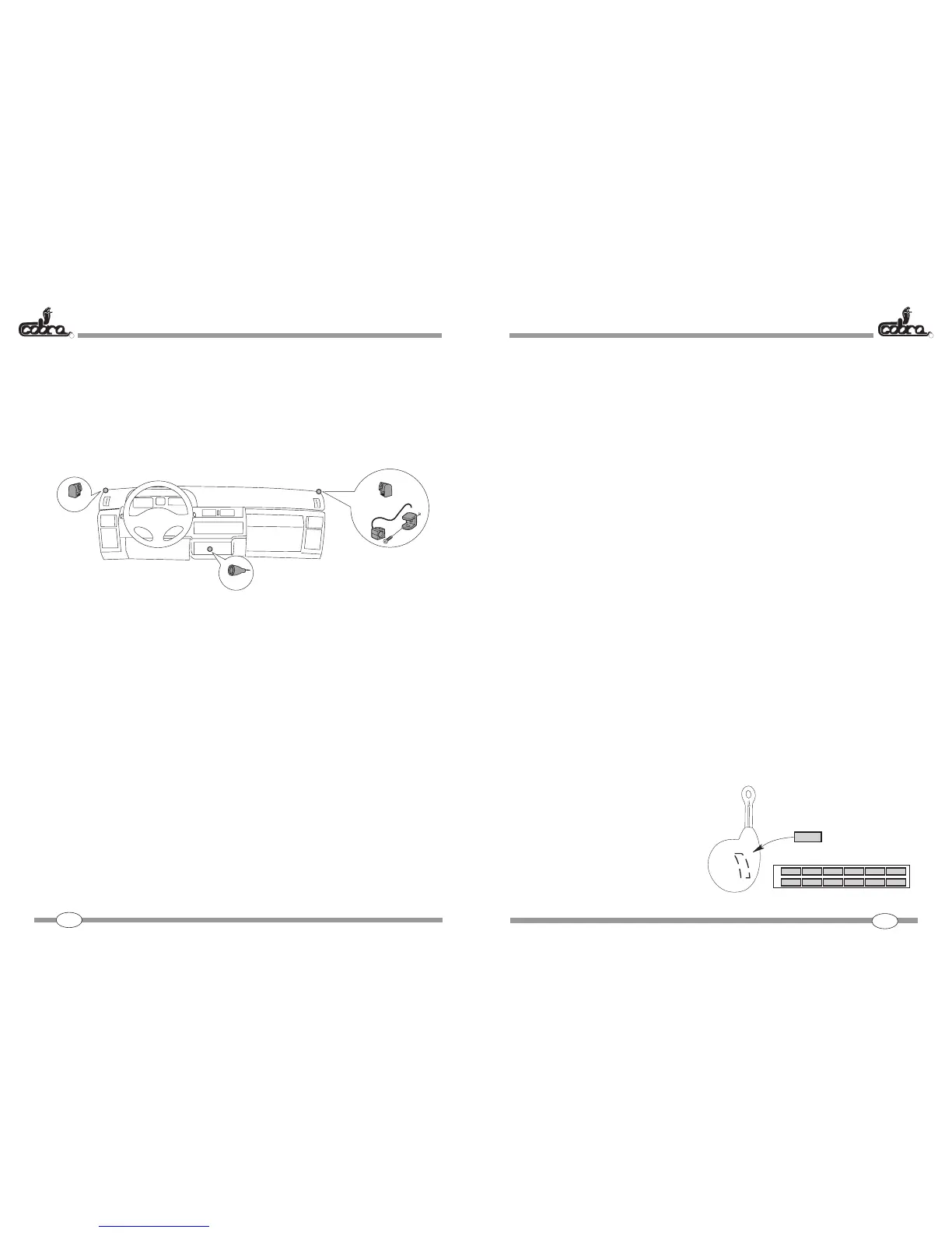
POSITIONING THE APPROVAL LABELSPOSITIONING THE APPROVAL LABELS
POSITIONING THE APPROVAL LABELSPOSITIONING THE APPROVAL LABELS
POSITIONING THE APPROVAL LABELS
The radio controls are supplied with homologation numbers for Germany and UK
already printed.
The other approvals are include on the labels supplied in the kit. Just choose the label
bearing the initial of your country and apply it as indicated in the figure
NOTE: The remaining labels must not be used.
46 47
B
B
A
 Loading...