R
R
GB
GB
1 1 1 1
2 2 2
2
3 3 3
MODE A
MODE B
MODE C
DATA TABLESDATA TABLES
DATA TABLESDATA TABLES
DATA TABLES
signalling that the PIN is correct and that the electronic key has been identified.
6.6.
6.6.
6. Keep pressed the remote control A button for 5 seconds. The LED will go OFF and
then it will inform you by a long blink that you are positioned in the mode table.
A group of faster blinks identify the selected mode: 1 blink means mode A, 2 blinks mean
mode B and so on. Press button A of the remote control to change from one mode to the
next as soon as the number of blinks corresponds to the selected mode.
Press button B of the remote control to confirm the selected mode; the group of blinks will
become slow to show that the choosen mode as been activated.
If you don't want to change the corrent setting or you don't remember the original setting,
don't press the remote control B button and proceed turning the ignition key OFF; in this
way you will mantain the courrent setting.
The way of blinking of the LED is the following:
Turn the ignition key OFF and then ON to go to the next table. The LED will go OFF
and then it will inform you by two long blinks that you are positioned in the function
table. As explained for the mode table (remote control A button for the selection and B
button for confirmation) you can choose the more suitable setting for your application.
Turning the ignition key ON and OFF again you can program the buzzer volume the
LED will inform you by three long blinks that you can adjust the buzzer volume:
by pressing the remote control A button the volume increases while pressing B button
decreases. Every time you press a button the buzzer will sound to let you check the
new volume level.
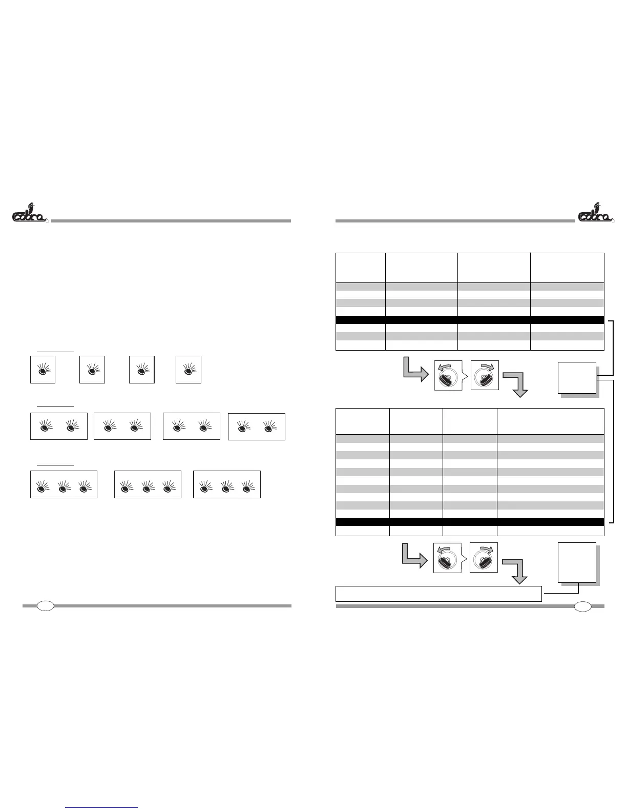
MODE TABLEMODE TABLE
MODE TABLEMODE TABLE
MODE TABLE
Mode
A = 1 blink
B = 2 blinks
C = 3 blinks
D = 4 blinks
E = 5 blinks
F = 6 blinks
G = 7 blinks
H = 8 blinks
O
F
F
CHIAVE OFF
KEY OFF
O
N
CHIAVE ON
KEY ON
Passive Arming
(Immobiliser)
ON
ON
ON
ON
ON
ON
OFF
OFF
OFF
OFF
OFF
OFF
Active Arming
ON
ON
ON
OFF
OFF
OFF
ON
ON
ON
OFF
OFF
OFF
FUNCTIONS TABLEFUNCTIONS TABLE
FUNCTIONS TABLEFUNCTIONS TABLE
FUNCTIONS TABLE
white/red wire outlet selection
(siren/horn)
continuous
intermittent
output controlled by B button
continuous
intermittent
output controlled by B button
continuous
intermittent
output controlled by B button
continuous
intermittent
output controlled by B button
Function
F1 = 1 blink
F2 = 2 blinks
F3 = 3 blinks
F4 = 4 blinks
F5 = 5 blinks
F6 = 6 blinks
F7 = 7 blinks
F8 = 8 blinks
F9 = 9 blinks
F10 = 10 blinks
F11 = 11 blinks
F12 = 12 blinks
O
F
F
CHIAVE OFF
KEY OFF
O
N
CHIAVE ON
KEY ON
Buzzer Volume : 0 ÷ MAX
50 51
window closing
time
(brown/white wire)
controlled by TX
24 s
24 s
controlled by TX
controlled by TX
24 s
24 s
controlled by TX
CDL Closing Relay
operating time
(violet wire)
1 s
1 s
24 s
controlled by TX
1 s
1 s
24 s
controlled by TX
Voltage Drop sensor
ON
ON
ON
ON
OFF
OFF
OFF
OFF
Factory
Set-up
Factory
Set-up
VOL = 0
 Loading...