15
Part 6 Gas Conversion
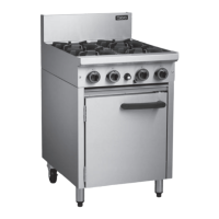
Aeration Adjustment
1. Check / adjust the main burner aeration gap.
This gap should be set to the dimensions shown
in the 'Gas Specification Tables' at the end of this
section.
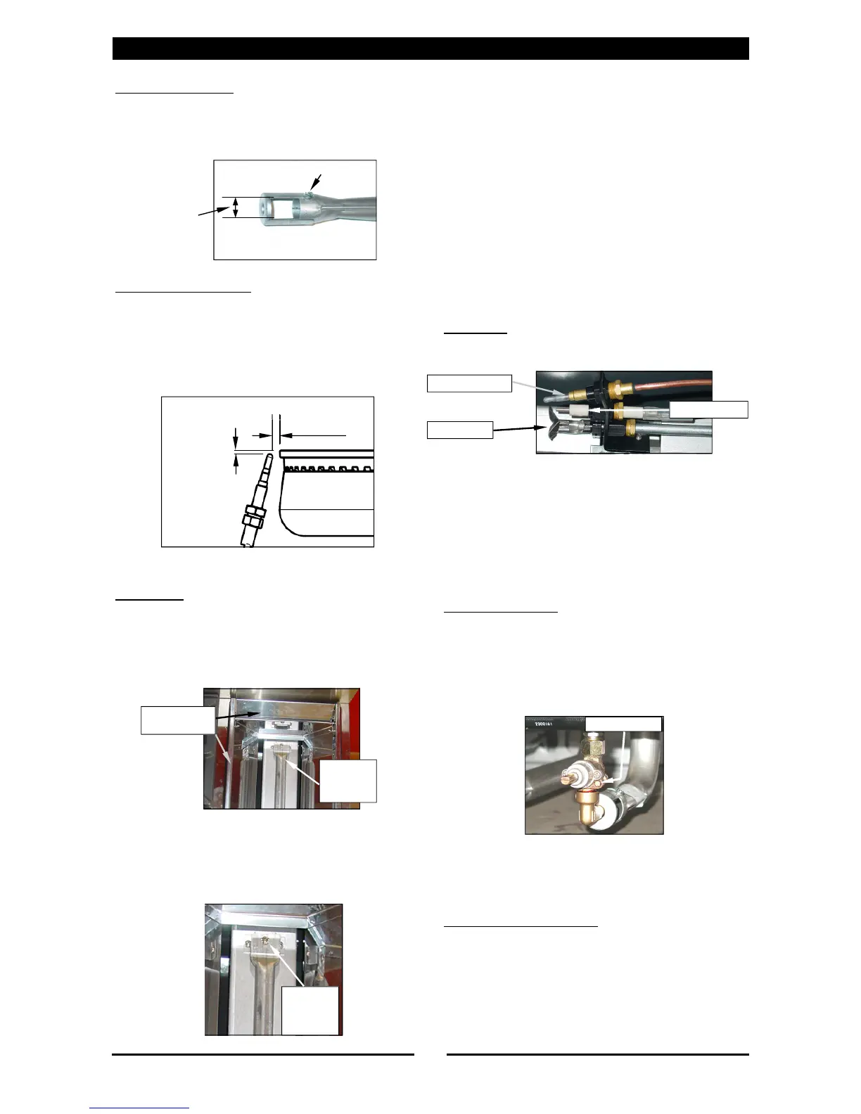
Thermocouple Location
1. Check that the thermocouple is correctly
located and that the gap between the
thermocouple and the main burner is as shown
in the diagram below.
2. Check that the thermocouple connection to the
gas valve is tight.
Griddle
Main Burner
1. With the gas supply turned off at the main
supply, remove the griddle plate section by
lifting it straight off the Cooktop.
2. Remove the gas control heat shield from around
the griddle burner, this is just a push in fit.
3. Disconnect the piezo igniter from the mounting
bracket. (For access purposes).
4. Remove the main burner from the burner box by
removing the securing screw at the end of the
burner, this will reveal the main burner injector.
5. Remove and replace the main burner injector
with correct size injector. Refer to the ‘Gas
Specifications’ table at the end of this section,
for correct injector sizes.
6. Refit the burner to the griddle burner box.
7. Refit the gas control heat shield to the griddle
burner box.
8. Refit griddle plate section to the top of Cooktop.
9. Check the thermocouple connection the gas
valve is tight.
10. Repeat Items 1 to 9 for all griddle main burners.
11. Turn ‘ON’ the gas supply at the mains, re-light
the griddle burners and check the flame size on
the ‘LOW’ flame position.
Pilot Burner
1. Disconnect the pilot supply tube from the pilot
burner.
2. Remove the existing pilot injector and replace
with the correct size for the gas being used.
Refer to the ‘Gas Specifications’ table at the
end of this section, for correct injector sizes.
3. Re-connect pilot supply tube to the pilot burner.
4. Refit the piezo igniter to the mounting bracket.
5. Repeat Items 1 to 4 for all griddle pilot burners.
Low Fire Adjustment
1. To adjust the griddle burner ‘LOW’ fire
adjustment, remove the griddle gas control
knobs from the front of the control panel.
2. Adjust the low fire adjustment screw on the
griddle gas control valve only, to obtain the
desired flame size.
NOTE:
The ‘Low Fire Adjustment Screw’ should be sealed
with coloured paint on completion of the low fire
adjustment.
Thermocouple Connection
1. Check that the thermocouple connection to the
gas valve is tight.
Low Fire Screw
Piezo Igniter
Thermocouple
Pilot Burner
Gas Control
Heat Shield
Burner
Securing
Screw
Burner
Securing
Screw
Refer to 'Gas
Specification
Tables'
Adjustment Screw
3 ±1 mm
2 ±1 mm
 Loading...