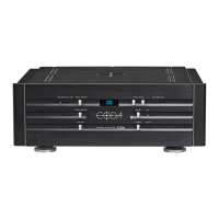
22
3.4 Signal inputs
The LINUS12C amplier oers two dierent input signal sources:
Analog
In this mode the analog signals connected to the XLR input connectors will be used as input signal.
LiNET
With the LiNET setting the input signals are taken from the LiNET Digital Audio interface.
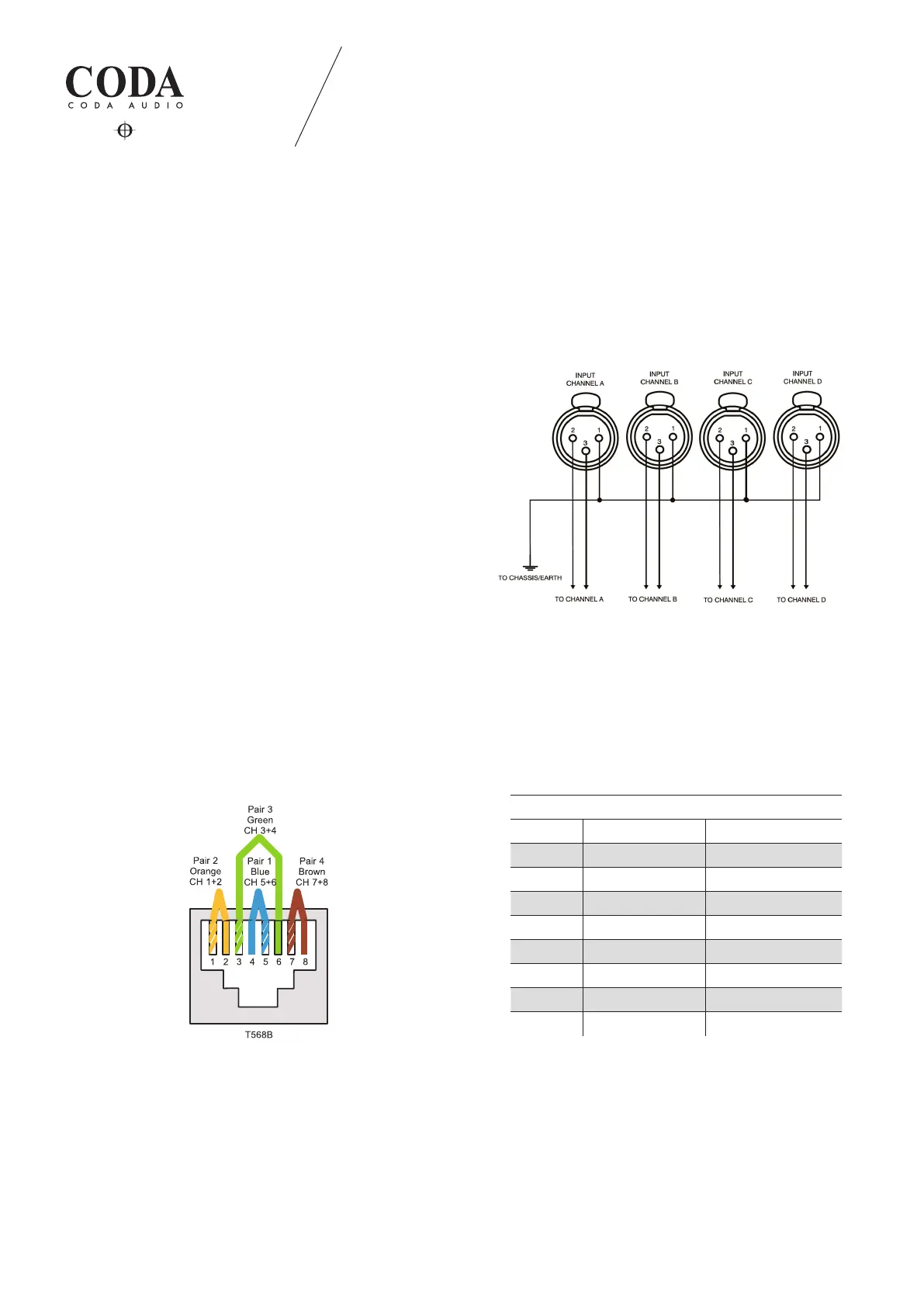
3.4.1 Analog input
XLR:
Pin 1 = Ground (lifted via 15 0 resistor to chassis/earth)
Pin 2 = Hot (in polarity, "+")
Pin 3 = Cold (out of polarity, "-")
We suggest to always use symmetrically (balanced) shielded
cable to connect the amplier.
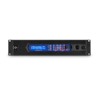
3.4.2 LiNET AES/EBU input/output
Eight audio channels are arranged in four AES/EBU pairs. The AES/EBU input and output connectors allow you to receive
and send multichannel digital audio streams to other AES/EBU-compatible devices (like other LINUS12C ampliers for ex-
ample). Please note that although the AES/EBU and Ethernet connectors use the same connector type (RJ45), the physical
transmission protocols are dierent. So any direct connection between the AES/EBU connectors and standard Ethernet
con nectors will not work.
LINUS12C 3. INSTALLATION
LiNET AES/EBU RJ45 pin wiring
RJ45-Pin Colour Channel (polarity)
1 orange-white 1/2 (+)
2 orange 1/2 (-)
3 green-white 3/4 (+)
4 blue 5/6 (+)
5 blue-white 5/6 (-)
6 green 3/4 (-)
7 brown-white 7/8 (+)
8 brown 7/8 (-)