8525B/8528 Technical Service Manual Adjustments 7-9
Publication No: 15-02036 Issue 6
7.3.8 Highpass Filters
Five adjustments are required for the highpass filters, one for the Broadcast
filter on the PA and Filter PCB and one each for the band selected filters on
the RF, Mixer, and Dual Synthesizer PCB.
To adjust these filters:
1. Connect a CRO, set for maximum sensitivity, across TP1 on the RF
Mixer and Dual Synthesizer PCB.
2. Connect a signal generator to the antenna socket.
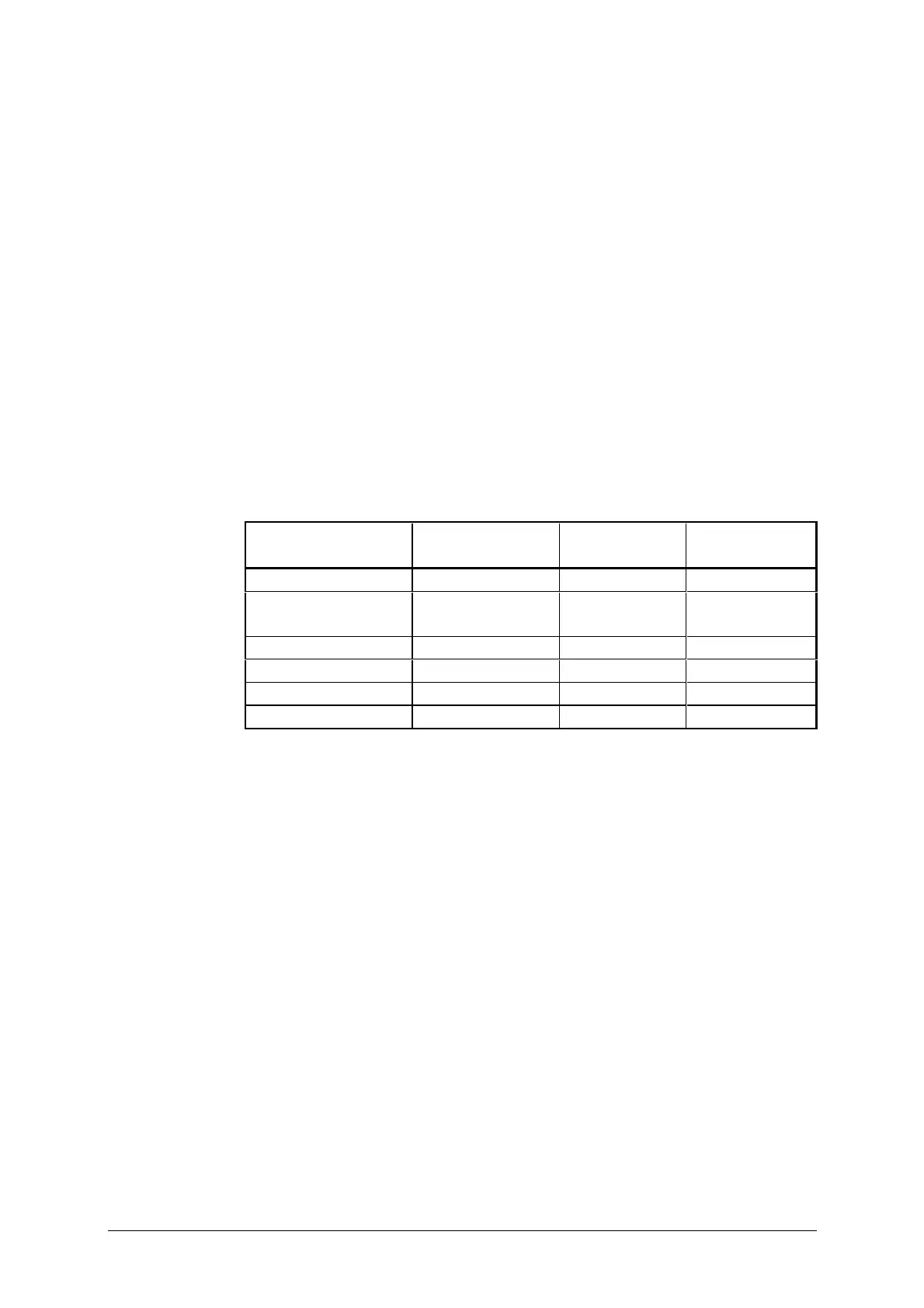
3. Select a channel within each of the Frequency ranges shown in table
below, in turn.
4. With each channel selected set the signal generator to the corresponding
Sig Gen Freq and adjust its output level until adequate indication is seen
on the CRO. (A starting level of 100mV is suggested.) Adjust the
corresponding inductor for minimum indication on the CRO.
Channel Frequency
(MHz)
Sig Gen Freq
(MHz
±
20kHz)
Inductor Location of
inductor
2 - 3.1 1.45 L14 PA & Filter PCB
3.1 - 4.8 2.2 L11 RF Mixer & Dual
4.8 - 7.5 3.4 L8 Synth PCB
7.7 - 11.6 5.3 L5 "
11.6 - 18 8.2 L2 "
18 - 24 10-12 No Adjustment "
Note: When Option LF is fitted, the first adjustment (2 – 3.1) must be
made with the signal generator frequency set to 1.18MHz.
 Loading...