Use of Antenna Splitters
Copyright © 2013 Coda Octopus Products Ltd
20
F175 MOTION Sensor - Trimble SPS361/SPS461 Integration
6 Use of Antenna Splitters
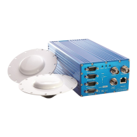
Two antennas are required in order for the F175 System to operate correctly. Usually, both
supplied Antcom antennas would be connected to the system. This allows the F175 System to
calculate a very accurate heading value. Antcom antennas would be connected to the system.
This allows the F175 System to calculate a very accurate heading value.
There may be some scenarios where additional antennas cannot be installed. In this case it is
possible to use active antenna splitters to split the external GNSS feed into both the external
GNSS receiver and the internal F175 receiver.
If an antenna splitter is used then there are a few important points to consider:
The F175 System supplies a 5V output to the antenna with up to 100mA supply. This is
probably enough to power both the antenna and the antenna splitter.
The F175 System receivers can work with both active and passive antennas. Care must
be taken when splitting the antenna signal. Only one junction of the split must pass the
d.c. supply voltage. We recommend that the junction that passes the d.c. supply voltage
should be connected to the external GNSS receiver. The junction that blocks the d.c.
supply voltage should be connected to the F175 System.
If the F175 System is supplying the power to the antenna splitter then both the antenna
and the antenna splitter need to work correctly from a 5V supply.
In dual-antenna configurations both antennas need to be of the same design or the
dual-antenna system will not work. Cable lengths should not be significantly different.
(E.g. 1m on one antenna and 15m on the other is not recommended.)
The F175 System has an extremely sensitive GPS receiver in it. High gain antennas can
sometimes have a signal that is too large for the F175 System. Antenna splitters often
contain some additional gain (to overcome cable and connector losses). Having an
antenna with a Low Noise Amplifier (LNA) gain of more than 40dB is not recommended.
This may be 35dB for the antenna and 5dB for the antenna splitter. Some GNSS
manufacturers’ antennas have a much higher LNA gain. For example the Trimble Zephyr
2 has a LNA gain of 50dB. If you wish to use this antenna in conjunction with the F175
System then you must use an appropriate attenuator. In the case of the Trimble Zephyr
2, an attenuator of 15 or 20 dB would be suitable. In the case of a Trimble GA530
antenna, a 10 dB attenuator is suitable.
CodaOctopus has tried and tested an antenna splitter from GPS Networking in a dual-antenna
configuration and we could not find a reduction in the performance. We recommend the
following antenna splitter models from GPS Neworking Inc,: ALDCBS1x2, ALDCBS1x4,
ALDCBS1x8
WARNING: By default these antenna splitters comes with a 14dB gain. It must be
ordered with a 3dB gain for use with the F175 System otherwise the overall gain is
likely to be too high. This gain cannot be ordered through the web and GPS
Networking must be contacted directly in order to have the 3dB gain.
The following diagram illustrates the antenna connections for the dual antenna Trimble
SPS461 system utilising dual Trimble GA530 antennas: