Connection Details
Copyright © 2013 Coda Octopus Products Ltd
10
F175 MOTION Sensor - Trimble SPS361/SPS461 Integration
2 Connection Details
The F175 System should be connected to the Trimble SPS361/SPS461 using one of the RS232
serial ports. On the F175 System the “External GNSS” connector is used. On the Trimble
SPS361/SPS461 receiver any of the serial ports can be used.
The Trimble SPS361/SPS461 are supplied with a combined power/ethernet/serial cable. The 9-
way connector on this cable is suitable for connecting the Trimble SPS361/SPS461 to a
standard 9-way serial port on a PC. However a RS232 NULL Modem connector is require to
connect the Trimble SPS361/SPS461 to the F175 System.
Power to the GPS receiver and power to the F175 System are wired separately to each
product. A common ground should be used to avoid ground problems.
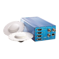
Figure 1: Connectors on the Trimble SPS361/SPS461
TNC (450 MHz
Internal Radio)
Reverse polarity
TNC (900 MHz
internal radio)
Not installed,
system without
internal radio
Connect to the radio antenna.
NOTE: This is an optional extra that is not present on the
default system.
Connection to GNSS antenna 1 for position. When connected to
a GA530 antenna, it will provide MSK Beacon signal.
NOTE: Marinestar correction service are only available on
this antenna port.