920-0505-00 Rev. B
Page 3 of 12
Notes:
1. Larger wires and tight connections will provide longer service life for components. For high current wires it
is highly recommended that terminal blocks or soldered connections be used with shrink tubing to protect
the connections. Do not use insulation displacement connectors (e.g., 3M Scotchlock type connectors).
2. Route wiring using grommets and sealant when passing through compartment walls. Minimize the
number of splices to reduce voltage drop. High ambient temperatures (e.g., under-hood) will signicantly
reduce the current carrying capacity of wires, fuses, and circuit breakers. All wiring should conform to the
minimum wire size and other recommendations of the manufacturer and be protected from moving parts
and hot surfaces. Looms, grommets, cable ties, and similar installation hardware should be used to anchor
and protect all wiring.
3. Fuses or circuit breakers should be located as close to the power takeoff points as possible and properly
sized to protect the wiring and devices.
4. Particular attention should be paid to the location and method of making electrical connections and splices
to protect these points from corrosion and loss of conductivity.
5. Ground termination should only be made to substantial chassis components, preferably directly to the
vehicle battery.
6. Circuit breakers are very sensitive to high temperatures and will “false trip” when mounted in hot
environments or operated close to their capacity.
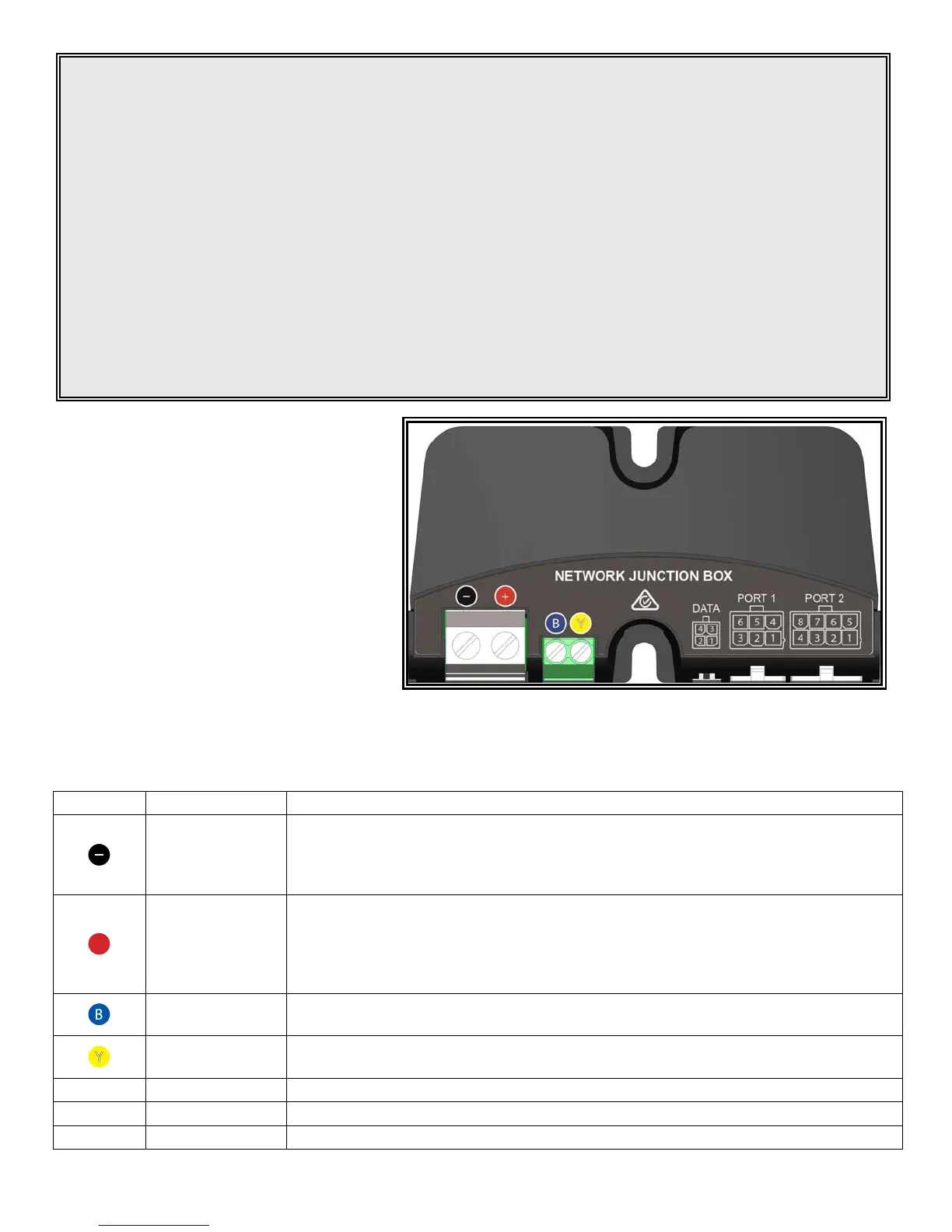
REF PORT DESCRIPTION
Black screw
terminal
Connect the Black ground wire from the Pursuit lightbar’s six conductor cable and
vehicle ground connection, insert both into the screw terminal and tighten. Use a good
chassis ground point or the battery negative terminal, using the shortest possible wire
length with a 10 AWG (4.5mm²) automotive wire.
+
Red screw
terminal
Connect the Red wire from the Pursuit lightbar’s six conductor cable and vehicle power
connection, insert both into the screw terminal and tighten. Use a 10 AWG (4.5mm²)
automotive wire from an external fused or circuit breakered source, using the shortest
possible wire length. The recommended external fuse size is 30A. Do not connect this
power wire until all other connections have been made to the unit.
Blue screw
terminal
Connect the Blue wire from the Pursuit lightbar’s cable. This wire connects directly to
the lightbar’s internal controller and should never be connected to power.
Yellow screw
terminal
Connect the Yellow wire from the Pursuit lightbar’s cable. This wire connects directly
to the lightbar’s internal controller and should never be connected to power.
DATA 4 Way Socket Connect the C3Pro Conguration Programmer to this port when programming.
PORT 1 6 Way Socket See tables below for wire colors and functions.
PORT 2 8 Way Socket See tables below for wire colors and functions.
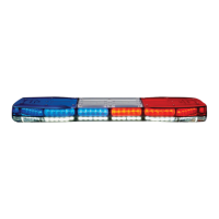
The Pursuit lightbar is controlled by the Code 3
Network Junction Box designed for multi-voltage
operation. Before proceeding with installation,
plan all cable routing and wiring carefully.
The Junction box can be mounted by screwing it
into any at surface using the 2 x
supplied screws,
preferably with a drip loop so it is not possible for
water to run down the cables into the unit.
THE JUNCTION BOX IS NOT WATERPROOF, IT
MUST BE MOUNTED WITHIN THE VEHICLE CABIN.
Network Junction Box Instructions
Input Voltage Range 10-30 VDC
Current Draw - Standby (Typ.) 14 mA
Ambient Operating Temperature -20 to +65 °C
Specications
 Loading...