Page 3 of 8
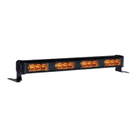
A variety of ash patterns may be chosen for the light head. The Multi Color light heads are split vertically as separate lighted areas that may
be chosen to operate alternately. The areas are denoted by: Primary color 1&3 (color1 on the left side and color3 on the right, typically the
same color) and Secondary color 2&4 (color2 on the left side and color4 on the right, typically the same color). This allows for patterns that
ash right-left using various multiple color combinations.
A separate ash pattern may be assigned for the power wires red, white, or both connected together and the pattern operated depending
which wire or wires are energized. Power the red or the white wires (or both together) then use the pattern select blue wire (touch to ground)
to select the chosen ash pattern from the list below. See the legend at the top of the pattern list for compliance with various standards.
Pattern Select Operation:
The light head ash pattern may be changed by touching the Blue wire to ground for the following intervals (while the light head is ashing):
NOTE: The blue wire must be disconnected from any voltage when not activating DIM nor changing ash patterns.
- When the light head signal becomes steady, disconnect the Blue wire and the ash pattern will increment by one pattern.
- When the light head signal becomes steady, then goes o, disconnect the Blue wire and the ash pattern will decrement by one pattern.
- When the light head signal becomes steady, then goes o, then becomes steady again, disconnect the Blue wire and the ash pattern will
reset to the factory default pattern.
- When the light head signal becomes steady, then goes o, then becomes steady again, then goes o again, disconnect the Blue wire and
the ash pattern will become set to the steady burn mode.
Flash Patterns:
For patterns that meet SAE J595 Class1 requirements for Red, Blue, Amber, and White, see S in chart!
For patterns that meet California Title 13 Class B requirements for Red, Blue, and Amber, see C in chart!
For patterns that meet ECE R65 Class 2 Cat X (day & night) requirements for Red, Blue, Amber see E2 in chart!
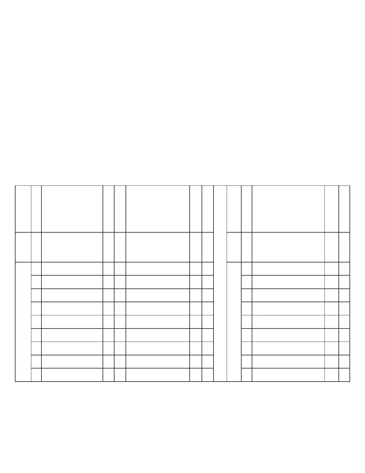
Flash Patterns XTP4DS Multi Color:
PATTERN
GROUP
PATTERN NO
FLASH PATTERN
RED WIRE
LED Primary Color
UP 1&3, DN 5&7
SYNC
Complies with
FLASH PATTERN
WHITE WIRE
LED Secondary Color
UP 2&4, DN 6&8
SYNC
Complies with
PATTERN
GROUP
PATTERN NO
FLASH PATTERN
RED & WHITE WIRE (to-
gether)
LED Primary Color
UP 1&3, DN 5&7
LED Secondary Color
UP 2&4, DN 6&8
SYNC
Complies with
0
1-Default
Cycle Flash Color
1&3&5&7 only
no
Cycle Flash Color
2&4&6&8 only
no 0
1-Default
Steady Burn Color 1&3&5&7
only
no
1
2
Single 75FPM Ph1
Color 1&3&5&7 only
yes SC
Single 75FPM Ph1 Color
2&4&6&8 only
yes SC
1
2
Single 75FPM Rt-Lt 1&5 Alt
4&8
yes S
3
Single 75FPM Ph2
Color 1&3&5&7 only
yes SC
Single 75FPM Ph2 Color
2&4&6&8 only
yes SC 3
Single 75FPM Rt-Lt 3&7 Alt
2&6
yes S
4
Single 75FPM Alt
1&3&5&7 with 2&4&6&8
yes SC
Single 75FPM Alt
2&4&6&8 with 1&3&5&7
yes SC 4
Single 75FPM Diagonal 1&7
Alt 4&6
yes S
5
Single 75FPM Up-Dn
1&3 Alt 5&7 only
yes S
Single 75FPM Up-Dn
2&4 Alt 6&8 only
yes S 5
Single 75FPM Diagonal 3&5
Alt 2&8
yes S
6
Single 75FPM Up-Dn
1&3 Alt 6&8 only
yes S
Single 75FPM Up-Dn
5&7 Alt 2&4 only
yes S 6
Single 75FPM CCW
1&3&5&7 Alt 2&4&6&8
no
7
Single 75FPM Rt-Lt 1&5
Alt 3&7
yes S
Single 75FPM Rt-Lt 2&6
Alt 4&8
yes S 7
Single 75FPM CCW
2&4&6&8 Alt 1&3&5&7
no
8
Single 75FPM Diagonal
1&7 Alt 3&5
yes S
Single 75FPM Diagonal
2&8 Alt 4&6
yes S 8
Single 75FPM CW 1&3&5&7
Alt 2&4&6&8
no
9
Single 75FPM CCW
1&3&5&7 only
no
Single 75FPM CCW
2&4&6&8 only
no 9
Single 75FPM CW 2&4&6&8
Alt 1&3&5&7
no
10
Single 75FPM CW
1&3&5&7 only
no
Single 75FPM CW
2&4&6&8 only
no
 Loading...