EasyManua.ls Logo

Code 3 XTP Series - User Manual

Code 3 XTP Series
8 pages
Print Icon
To Next Page IconTo Next Page
Loading...
Page 1 of 8
Installation and Operation Instructions
XTP SERIES LIGHT HEADS Multi Color
IMPORTANT! Read all instructions before installing and using. Installer: This manual must be delivered to the end user.
WARNING!
Failure to install or use this product according to manufacturers recommendations may result in property damage, serious injury, and/
or death to those you are seeking to protect!
Specications:
Size: XTP4MC 0.62” H x 1.39” W x 4.72” L
XTP6MC 0.62” H x 1.39” W x 6.21” L
Weight: XTP4MC 0.13 lb (0.06 Kg)
XTP6MC 0.18 lb (0.08 Kg)
Input Voltage: 12-24VDC
Input Current: 0.8A Max @ 12 VDC NOMINAL
Temp. Range: -40ºC to 65ºC
-40ºF to 149ºF
Do not install and/or operate this safety product unless you have read and understood the safety information
contained in this manual.
1. Proper installation combined with operator training in the use, care, and maintenance of emergency warning devices are essential to
ensure the safety of emergency personnel and the public.
2. Emergency warning devices often require high electrical voltages and/or currents. Exercise caution when working with live electrical
connections.
3. This product must be properly grounded. Inadequate grounding and/or shorting of electrical connections can cause high current arcing,
which can cause personal injury and/or severe vehicle damage, including re.
4. Proper placement and installation is vital to the performance of this warning device. Install this product so that output performance of
the system is maximized and the controls are placed within convenient reach of the operator so that they can operate the system without
losing eye contact with the roadway.
5. Do not install this product or route any wires in the deployment area of an air bag. Equipment mounted or located in an air bag
deployment area may reduce the e󰀨ectiveness of the air bag or become a projectile that could cause serious personal injury or death.
Refer to the vehicle owners manual for the air bag deployment area. It is the responsibility of the user/operator to determine a suitable
mounting location ensuring the safety of all passengers inside the vehicle particularly avoiding areas of potential head impact.
6. It is the responsibility of the vehicle operator to ensure daily that all features of this product work correctly. In use, the vehicle operator
should ensure the projection of the warning signal is not blocked by vehicle components (i.e., open trunks or compartment doors),
people, vehicles or other obstructions.
7. The use of this or any other warning device does not ensure all drivers can or will observe or react to an emergency warning signal.
Never take the right-of-way for granted. It is the vehicle operators responsibility to be sure they can proceed safely before entering an
intersection, drive against tra󰀩c, respond at a high rate of speed, or walk on or around tra󰀩c lanes.
8. This equipment is intended for use by authorized personnel only. The user is responsible for understanding and obeying all laws
regarding emergency warning devices. Therefore, the user should check all applicable city, state, and federal laws and regulations. The
manufacturer assumes no liability for any loss resulting from the use of this warning device.

Other manuals for Code 3 XTP Series

Question and Answer IconNeed help?

Do you have a question about the Code 3 XTP Series and is the answer not in the manual?

Summary

Product Specifications

Installation and Mounting

Wiring Instructions

Dim Control Notes

The light head intensity can be reduced. Blue wire to positive reduces intensity to 25% (SAE) or 55% (ECE).

Synchronization and Phase Notes

Up to 32 light heads can be synchronized using yellow wires. Set flash patterns and rates before connecting.

Flash Patterns

Pattern Selection Operation

Describes how to change flash patterns by touching the blue wire to ground for specific intervals.

Troubleshooting

Check Power and Connections

Verify power source activation and check all connections for open or shorted circuits.

Blue Wire to Ground

Permanently connecting the blue wire to ground disables the light head, regardless of pattern.

Dim Function Issues

If dim function fails, verify the blue wire is correctly connected to positive.

Sync Function Issues

If sync is erratic and not used, verify the yellow wire is not connected to positive.

Warranty Information

Limited Warranty Policy

Product conforms to specifications for sixty (60) months from date of purchase. Voids if tampered or improperly installed.

Exclusion of Other Warranties

Disclaims implied warranties of merchantability, quality, or fitness for a particular purpose.

Remedies and Limitation of Liability

Sole liability is repair/replacement/refund. Excludes lost profits, property damage, and consequential damages.

Product Returns

Contact factory for RGA number before returning. Use sufficient packing materials to avoid transit damage.

Overview

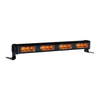
This document provides installation and operation instructions for the CODE 3 XTP SERIES LIGHT HEADS Multi Color. These are emergency warning devices designed for vehicle applications.

Function Description

The XTP Series Light Heads are multi-color emergency warning devices. They feature a split vertical design, allowing for separate lighted areas (Primary color 1&3 on the left, Secondary color 2&4 on the right) which can operate alternately. This design enables various multiple color combinations and right-left flashing patterns. The light heads can be powered via red or white wires (or both) and their flash pattern selected using a blue pattern select wire (touching to ground). The device supports synchronization of up to 32 light heads by connecting their yellow wires, allowing for simultaneous or alternating flashes between groups of light heads. A dim control feature is also included, which reduces light intensity when the blue wire is connected to positive.

Important Technical Specifications

  • Size:
    • XTP4MC: 0.62" H x 1.39" W x 4.72" L
    • XTP6MC: 0.62" H x 1.39" W x 6.21" L
  • Weight:
    • XTP4MC: 0.13 lb (0.06 Kg)
    • XTP6MC: 0.18 lb (0.08 Kg)
  • Input Voltage: 12-24VDC
  • Input Current: 0.8A Max @ 12 VDC NOMINAL
  • Temperature Range: -40°C to 65°C (-40°F to 149°F)
  • Mounting: Uses a bezel as a template for mounting holes. Self-tapping #6 x 0.75" screws are typically used with 0.125" diameter holes. A minimum 0.50" diameter hole is required for wires, with grommet and RTV sealant recommended.
  • Wiring:
    • RED: Positive (5A fuse required)
    • WHITE: Positive (5A fuse required)
    • BLACK: Negative
    • BLUE: Pattern select to negative / Dim control to positive
    • YELLOW: Synchronized Function (Up to 32 units can be synchronized)
  • Dim Control: Connecting the blue wire to positive reduces intensity to 25% for SAE patterns and 55% for ECE patterns. The blue wire must be disconnected when not activating DIM or changing flash patterns.
  • Flash Patterns: A wide variety of flash patterns are available, categorized by PATTERN GROUP and compliance with standards such as SAE J595 Class1, California Title 13 Class B, ECE65 Class1 Cat X, and ECE65 Class2 Cat X. Patterns can be selected by momentarily touching the blue wire to ground.
  • Warranty: Manufacturer provides a Limited Warranty of Sixty (60) months from the date of purchase.

Usage Features

  • Multi-Color Capability: The light heads offer multi-color functionality with primary and secondary color areas, allowing for diverse warning patterns.
  • Pattern Selection: Flash patterns are easily changed by touching the blue wire to ground. The system allows for incrementing, decrementing, or resetting to default patterns based on the duration and sequence of grounding the blue wire. A steady burn mode is also available.
  • Synchronization: Up to 32 light heads can be synchronized for coordinated flashing. This is achieved by connecting the yellow wires of the units. The setup process involves selecting desired flash patterns for each light head (ensuring they have the same flash rate for synchronized units) and then connecting the yellow wires.
  • Dim Control: The light intensity can be reduced for night-time operation or specific conditions by connecting the blue wire to positive.
  • Versatile Powering: The light heads can be powered by either the red or white wire, or both, allowing for flexible integration into a vehicle's electrical system.
  • Authorized Personnel Use: This equipment is intended for use by authorized personnel only, who are responsible for understanding and obeying all relevant laws and regulations regarding emergency warning devices.

Maintenance Features

  • Installation Guidelines: Detailed instructions are provided for proper installation, including mounting surface selection, drilling, wiring, and sealing. Emphasis is placed on using grommets and sealant for wire routing, minimizing splices, and protecting wiring from moving parts and hot surfaces.
  • Grounding: Proper grounding to substantial chassis components (preferably directly to the vehicle battery) is crucial for preventing high current arcing and ensuring safety.
  • Fuse/Circuit Breaker Placement: Fuses or circuit breakers should be located as close as possible to the power takeoff points and properly sized to protect wiring and devices.
  • Connection Integrity: Recommendations include using terminal blocks or soldered connections with shrink tubing for high current wires to ensure longer service life and prevent corrosion and loss of conductivity. Insulation displacement connectors are not recommended.
  • Daily Checks: The vehicle operator is responsible for ensuring daily that all features of the product work correctly and that the warning signal is not blocked by vehicle components or obstructions.
  • Troubleshooting Guide: A dedicated section helps diagnose common issues, such as checking power source activation, positive and ground connections, proper use of the blue programming wire (not permanently connected to ground unless disabling the light head), correct connection of the blue wire for dim function, and ensuring the yellow wire is not connected to positive if sync function is not used.
  • Product Returns: Instructions are provided for returning products for repair or replacement, requiring a Return Goods Authorization Number (RGA) from the factory and proper packaging to prevent transit damage.

Code 3 XTP Series Specifications

General IconGeneral
BrandCode 3
ModelXTP Series
CategoryLighting Equipment
LanguageEnglish

Related product manuals