EasyManua.ls Logo

Code 3 CELS - User Manual

Code 3 CELS
17 pages
Print Icon
To Next Page IconTo Next Page
Loading...
INSTALLATION MANUAL
Read all instructions and warnings before installing and using.
This manual must be delivered to the end user of this equipment.
IMPORTANT:
For future reference record your product's serial no. here __________________________________________
INSTALLER:
CONTENTS:
Introduction .................................................................................................2
Installation, Mounting, & Wiring .............................................. ................3-5
Wiring Diagram Package 1 ........................................................................6
Wiring Diagram Package 2 ........................................................................7
Wiring Diagram Package 3 ........................................................................8
Wiring Diagram Package 4 ........................................................................9
Wiring Diagram Package 5 .......................................................................10
Wiring Diagram Package 6 .......................................................................11
Functionality-Flash Pattern Selection ..................................................12-13
Notes:...................................................................................................14-16
Warranty ..................................................................................................17
Question and Answer IconNeed help?

Do you have a question about the Code 3 CELS and is the answer not in the manual?

Summary

CELS Installation Manual Overview

Introduction to CELS System

Overview of the CELS system, its purpose, and benefits for emergency lighting control.

CELS Product Features and Components

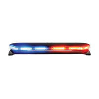
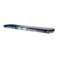
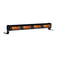
Details on CELS product features, available packages, and specific LED lighting components.

CELS Product Specifications

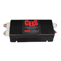
Technical specifications for the CELS control box, including dimensions, weight, and warranty.

Safety and Warning Guidelines

General Safety and Operational Warnings

Essential safety precautions for operating and installing the CELS system to ensure user and vehicle safety.

Installation and Environmental Hazard Warnings

Warnings regarding installation procedures, potential air bag interference, and electromagnetic interference (EMI).

Installation and Wiring Procedures

Mounting and General Wiring Instructions

Guidance on mounting the control box and initial wiring connections for the CELS system.

Wiring Light Heads

Specific instructions for wiring dual and single color XT4 and PAR36 light heads.

Critical Installation Warnings

Important warnings related to installation, including screw usage, mounting, and voltage application.

General Wiring Best Practices

CELS System Specific Wiring

Detailed wiring steps and considerations specific to the CELS system's connections.

Wiring Best Practices

Recommendations for wire gauge, connections, routing, and protection for longevity.

Grounding, Splicing, and RF Considerations

Procedures for proper ground connections, splicing techniques, and managing RF interference.

CELS System Features and Functionality

3-Level Flashing Feature

Explanation of the 3-level flashing patterns available for different packages.

Dim, Cruise, and ArrowStik Features

Details on the Dim, Cruise, and ArrowStik features and how they operate.

Advanced Feature Configuration

Rear Cutoff and Takedown Features

Operation and configuration of Rear Cutoff and Takedown features for enhanced control.

Steady Burn and Flash Pattern Selection

Configuration of the steady burn feature and method for selecting flash patterns.

Warranty and Product Returns

CELS Product Warranty Information

Details on the warranty coverage for CELS parts and components, including limitations.

Product Returns and Repair Process

Procedure for returning products for repair or replacement, including obtaining an RGA number.

Overview

This document is an installation manual for the Code 3 CELS (Coordinated Emergency Lighting System™) Control Box, a device designed for emergency vehicle lighting.

Function Description:

The CELS system is designed for interior mounting in vehicles and controls all emergency vehicle lighting to flash synchronously, programmable with a CC lightbar. It also offers dimming capabilities for the entire emergency lighting system. CELS provides enhanced control over vehicle lights to suit various situational needs and is available in five undercover lighting packages. The system allows for independent flash patterns from a lightbar if one is installed.

Important Technical Specifications:

  • Control Box Dimensions: 4 3/4" W x 8 1/2" L x 1 7/8" H
  • Control Box Weight: 1 lb.
  • Voltage: 12 Volts
  • Warranty: 5 Year LED Warranty
  • Current Draw (Packages 1-4): Average 12-15A, maximum 20A.
  • Fuse Sizing: Approximately 125% of the maximum Amp capacity in the supply line (e.g., a 30 Amp fuse for a maximum of 24 Amps).
  • Wire Gauge: Refer to the "Wire Gauge Selection Table 12 Volt Circuit" provided in the manual for appropriate wire sizes based on amperage and length of wire run. For power and ground wires, 12 gauge wire is recommended with 12 gauge butt splices and a 20 amp fuse on the power wire. Input and Front/Rear Output wires are 22 gauge and should be connected with 22 gauge butt splices.

Usage Features:

  • Packages:
    • Packages 1-4 include 4 types of lighting equipment and a control box.
    • Package 5 includes 3 types of lighting equipment and a control box.
    • Package 6 includes 1 type of lighting equipment and a control box.
  • Compatibility: The control box can be wired to any switching type system.
  • NarrowStik™ Functionality: Available with exterior rear window light (Citadel).
  • Dimming Capability: For all lighting equipment.
  • Synchronous Capability: For all lighting equipment.
  • Vehicle Compatibility: For use on Ford PI Utility and Chevy Tahoe vehicles.
  • LED Lighting Components:
    • SuperVisor U® with Torus LEDs (mounts inside windshield, no drilling).
    • Citadel™ LED Exterior Lighting Systems (fits under Rear Spoiler, no drilling).
    • PAR36 Fog Light with 7 LEDs per Head (4.25" diameter).
    • XT4S LED Light heads (4.52" wide).
  • Wiring:
    • CELS Dual Color XT4 & PAR36 Light Heads are "STEADY BURN ONLY" and rely on the CELS Controller for flash patterns. They have (3) control wires, (2) power wires (matching LED colors), and (1) black ground wire.
    • CELS Single Color XT4 & PAR36 Light Heads are "STEADY BURN ONLY" and rely on the CELS Controller for flash patterns. They have (2) control wires, (1) red power wire, and (1) black ground wire.
    • Do not apply 12 volts directly to the CELS box output wires to avoid damage.
    • Main power and ground wires should connect directly to the vehicle's battery, not to an auxiliary connection.
    • The Black/Red wire should be attached to ground after all programming is complete to prevent accidental flash pattern/program changes.
    • A Brown/White wire can be substituted for any CELS Output Wire to provide a CA Title 13 Steady Red Light Head feature, but should not be combined with other output wires.
  • 3-Level Flashing Feature: Flash patterns are based on 600-series lightbar software, configuring the entire bar with 7 combinations of 3-level inputs. This feature flashes Supervisor and Citadel heads, as well as XT4 and PAR36 heads (primaries only if secondaries are Takedowns). Patterns include NULL FLASH, NFPA QF, SLOW QF, FAST SGL, SLOW SGL, FAST DBL, SLOW DBL, VAR RATE SGL, and CYCLE. Defaults are L1=pattern 10, L2=pattern 2, L3=pattern 9.
  • Dim Feature: Dims all currently active outputs (except Supervisor Takedowns) to 25%. Does not affect Cruise function.
  • Cruise Feature:
    • Packages 1, 2, & 6: Turns on Citadel secondary-color end outputs (heads 1 and 6) and additional (PAR36 and XT4) secondary outputs.
    • Packages 3 & 4: Turns on Citadel primary-color end outputs (heads 1 and 6) and additional (PAR36 and XT4) secondary outputs.
    • Heads operate at 12.5% duty cycle. Not programmable. Overridden by other active features/inputs, except Dim and Rear Cutoff.
  • ArrowStik Feature: Enabled for Packages 1-4 & 6. Citadel primary-color outputs behave as a normal 6-head ArrowStik. Overrides Citadel ArrowStik and dual-color (flashing rear) outputs. Flash patterns are standard 800-series and 950-series, with a default of Mode 1, Medium speed for all four types.
  • Rear Cutoff Feature: Uses the RCUT input to cut off rear (Citadel) flashing (primary) outputs. Overrides 3-Level functionality to the rear. Not programmable. Unaffected by ArrowStik or Cruise functions.
  • Takedown Feature (Packages 1-5 only):
    • Takedown Flash: Flashes Supervisor Takedowns with patterns like NFPA QUAD, SLOW QUAD, FAST SGL, MED SGL, FAST DOUBLE, SLOW DOUBLE, VAR RATE SGL, and CYCLE (default is pattern 1).
    • Takedown Steady: Activates Supervisor Takedowns, and XT4/PAR36 secondaries if configured as Takedowns. Supervisor Takedown heads run at 100% duty cycle, and PAR36/XT4 secondary heads (if activated) run at 50% duty cycle.
    • Takedown Steady configuration options (default is pattern 2): Supervisor TD only, or Supervisor TD and PAR36/XT4 secondaries ("Flood" mode).
  • Steady Burn Feature: Functions like 600 series software, with jumpers on the CC board selecting L1, L1+L2, or L1+L2+L3 to activate the SB output (e.g., for a CA Steady Red feature). Jumper locations are shown in Figure-3.
  • Flash Pattern Selection: Touching the PGM wire to +12V for at least 50ms changes to the next pattern. Holding for approx. 4 seconds resets to factory default. Works if other modes are active via inputs: L1, L2, L3, L1+L2, L2+L3, L1+L2+L3, TDFL (Takedown flash pattern), TDSB (PAR36/XT4 secondaries in takedown steady burn).

Maintenance Features:

  • Installation: Mount the System Box inside the vehicle using customer-supplied screws in the (4) slots provided in the housing's base. Do not mount on the exterior.
  • Wiring Best Practices:
    • Use larger wires and tight connections for longer service life.
    • Use terminal blocks or soldered connections with heat shrink tubing for high current wires.
    • Do not use insulation displacement connectors (e.g., 3M® Scotchlock type).
    • Route wiring using grommets and sealant when passing through compartment walls.
    • Use "SXL" type wire in engine compartment for high ambient temperatures.
    • All wiring should conform to minimum wire size and manufacturer recommendations, protected from moving parts and hot surfaces.
    • Use looms, grommets, cable ties, and similar hardware to anchor and protect wiring.
    • Fuses or circuit breakers should be located as close to power takeoff points as possible and properly sized.
    • Avoid 1/4" diameter glass fuses for continuous duty above 15 AMPS.
    • Circuit breakers are sensitive to high temperatures and can "false trip."
  • Ground Connections: Terminate to substantial chassis components, preferably directly to the vehicle battery. Ensure clean connection points if using chassis ground. Grounding wire gauge must match or exceed the AWG Table. Avoid stacking multiple ground connections.
  • Splicing Connections: Use the correct wire stripper to ensure all strands remain intact. Do not under-strip or over-strip. Use appropriate crimping pliers and properly sized connectors/terminals (Butt Splices, Fork Terminals, Ring Terminals). Minimize splices to reduce voltage drop. Protect connections from corrosion and loss of conductivity (Wire Loom, Heat Shrink Tubing, Sealed Connectors).
  • RF Considerations: Do not locate the CELS Box close to an antenna or other RF/EM emitting device. Do not route cables or wires from CELS components within 18 inches of an antenna, antenna cable, radar unit, radio amplifier, or other RF/EM emitting device.
  • Troubleshooting: If questions or problems arise, contact Technical Assistance HOTLINE (314) 996-2800.
  • Product Returns: Contact the factory for a Return Goods Authorization Number (RGA) before shipping for repair or replacement. Pack securely to prevent damage.

Code 3 CELS Specifications

General IconGeneral
BrandCode 3
ModelCELS
CategoryLighting Equipment
LanguageEnglish

Related product manuals