Code Blue
•
259 Hedcor Street
•
Holland, MI 49423 USA
•
800.205.7186
•
www.codeblue.com
GU-157-AApage 46 of 76
CB 1 Series
Administrator Guide
3.4.2 Snap the nosecone into position over the outside edges of the blade hub.
3.4.3 Make sure all three edges of the nosecone snap over the edge of the blade hub. After
installation tug on the nosecone to make sure it is securely attached.
3.5 Fish the wires into the unit and connect them to the battery – Use the existing pull wire
and attach the solar panel, wind generator and antenna wires to pull down into the unit. Once
the wires are into the unit, separate them. Attach the supplied forks to each black and red wire.
The green wire should be attached to the existing ground lug on the bottom of the panel. One
set of wires will have white electrical tape approximately 8-10 inches from the end. These are
the solar panel wires.
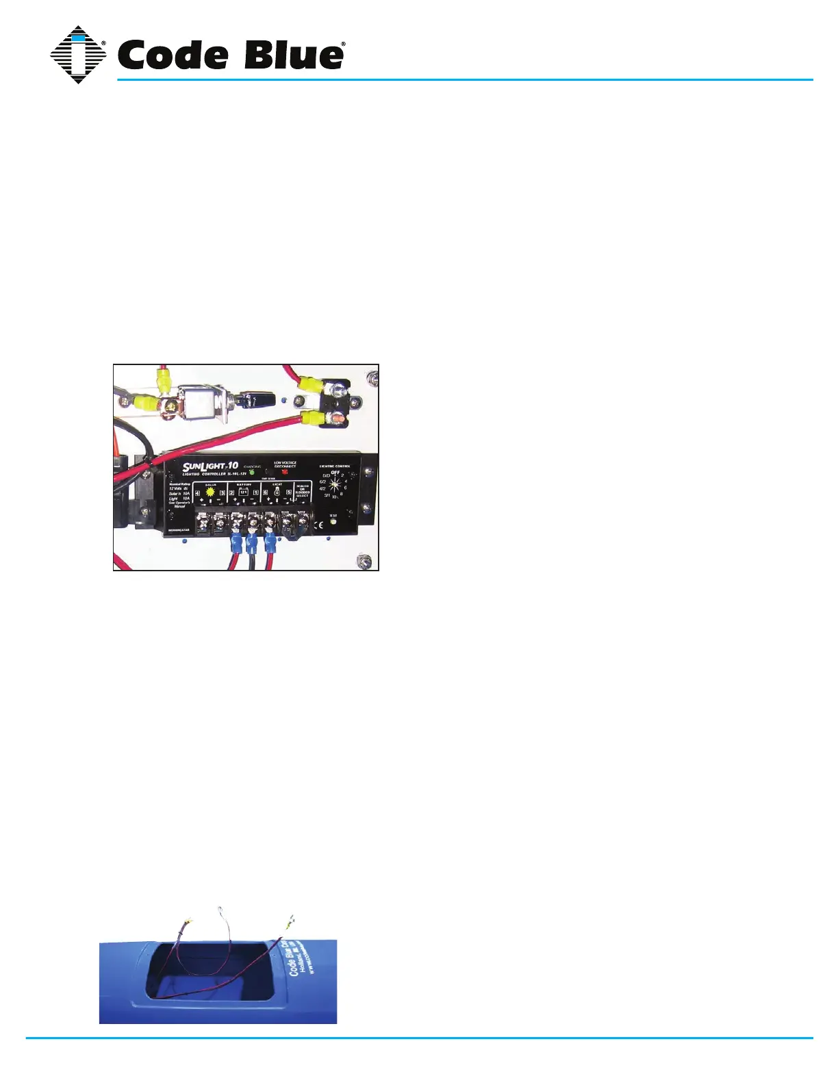
3.6 Attach the solar panel wires – Connect the red wire to the solar charge controller on the
positive (+) lug and the black wire on the negative (-) lug. These lugs are under the sunshine
icon (See Figure 3).
3.7 Attach the wind generator wires – Connect the
red wire to the center screw terminal on the stop switch.
Connect the black wire to the same screw terminal the
existing black wire is connected to (See Figure 3).
3.7.1 When the stop switch is pushed towards the panel
the unit is in charging mode.
3.7.2 When the stop switch is centered, it is not charging
and the blades are in a free spin mode.
3.7.3 When the stop switch is pulled toward the access
door, the blades will stop for maintenance.
4.0 INSTALL THE BATTERIES
NOTE: Batteries must be FULLY bench charged before installation.
WARNING: Reversing the battery wires (reversed polarity) will cause damage to the solar charge
controller, wind generator GSM and IP wireless circuits and is NOT covered by the warranty.
4.1 Place the batteries into the unit – Insert the battery shelf plates into the bottom access door.
One battery should be placed on each shelf.
4.2 Connect the wires – Connect the large gauge wires with yellow rings to the bottom battery
along with the smaller gauge blue ringed wires. Connect the red wires to the positive (+) lugs
on the batteries, then connect the black wires to the negative (-) lugs. Install the second bat-
tery shelf plate and insert the top battery. Connect the small gauge yellow ringed wires to the
battery. Connect the red wire to the positive (+) lugs on the batteries, then connect the black
wire to the negative (-) lugs (See Figure 4).
5.0 INSTALLING THE GSM CELLULAR UNIT
NOTE: A local cellular dealer must provide a SIM card before it can place calls.
5.1 Installation
5.1.1 Remove the GSM unit from its shipping box.