Deploy the PC and the 3D Sensor
Perform the following steps to deploy your PC and 3D-A5000 sensor:
1. Place your PC in a well-ventilated area.
2. Mount your sensor within cable-length of the PC. See Hardware Installation on page9 for measurements of the
mounting plate on the back of the sensor.
3. Connect the GigE cable of the sensor to the 10 Gigabit Ethernet adapter.
4. Connect your 3D-A5000 power cable to a 24V power supply.
Power cable pin assignments:
Pin Number Signals WireColor
1 +24VDC Red
2 Ground Black
3 Reserved
4 Reserved
5. Connect an optional hardware trigger.
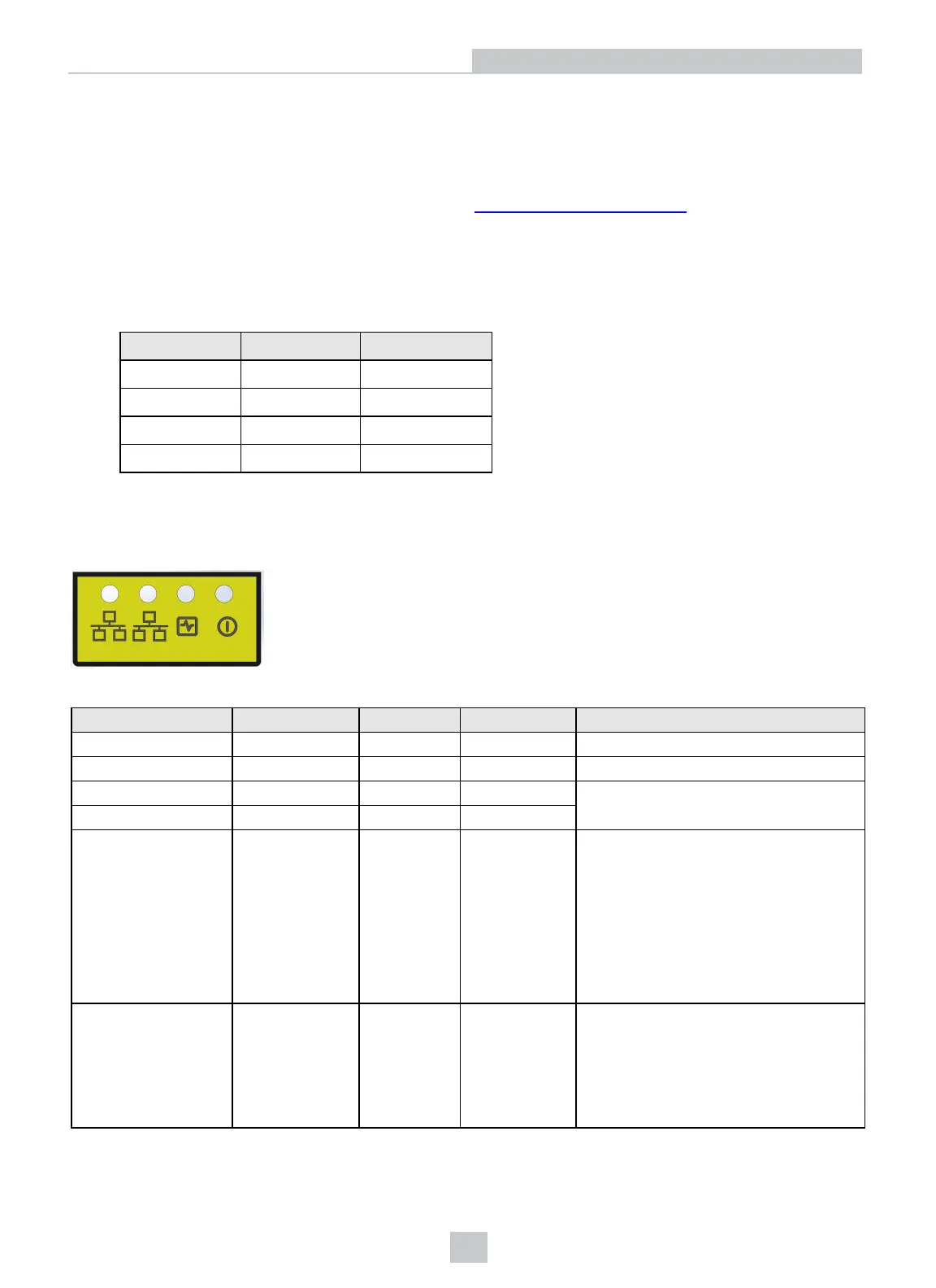
LED Indicators
Refer to the following table for a description of the status LED indicators on the front panel of the 3D sensor:
Green (Ethernet) Yellow (Ethernet) Red Green Details
OFF OFF OFF OFF Power Off
ON ON ON ON Powering Up
OFF OFF ON OFF Booting
OFF OFF ON ON
ON/OFF
ON
(pulses)
OFF
ON
(pulses)
System OK
Green ON, pulses briefly every 5 seconds
Yellow ON if Ethernet link connected at
any speed, pulses with Ethernet packets
sent or received
Green (Ethernet)ON if Ethernet connected
at 10 Gbps
N/A N/A FLASH FLASH
Firmware Update Required
Green and Red flash alternately indicating
an interrupted firmware update.
Sensor will not acquire images until a
successful firmware update is complete.
10
Hardware Installation
 Loading...