I/O Cable
The following table describes the 3D-A5000 I/O cable:
Pin
Number
Signal WireColor
1 READY+ Yellow
2 Reserved White/Yellow
3 Reserved Brown
4 READY- White/Brown
5 TRIGGER_IN+ Violet
6 TRIGGER_IN- White/Violet
7 Reserved Red
8 Reserved Black
9 TRIGGER_OUT+ Green
10 TRIGGER_OUT- Orange
11 MISSED_TRIGGER+ Blue
12 MISSED_TRIGGER- Grey
Hardware Triggers
The acquisition trigger input to the 3D sensor is opto-isolated, and the sensor will respond to a trigger event when the
voltage difference between the TRIGGER+ and TRIGGER- inputs exceeds 10V.
Specification Description
V
IH
±10 – ±28 V
V
IL
0 – ±5 V
I
TYPE
@ 12 VDC, 4 mA
@ 24 VDC, 8 mA
Delay 50 µs maximum latency between leading edge of trigger and start of acquisition. Input pulse
should be a minimum of 1ms wide.
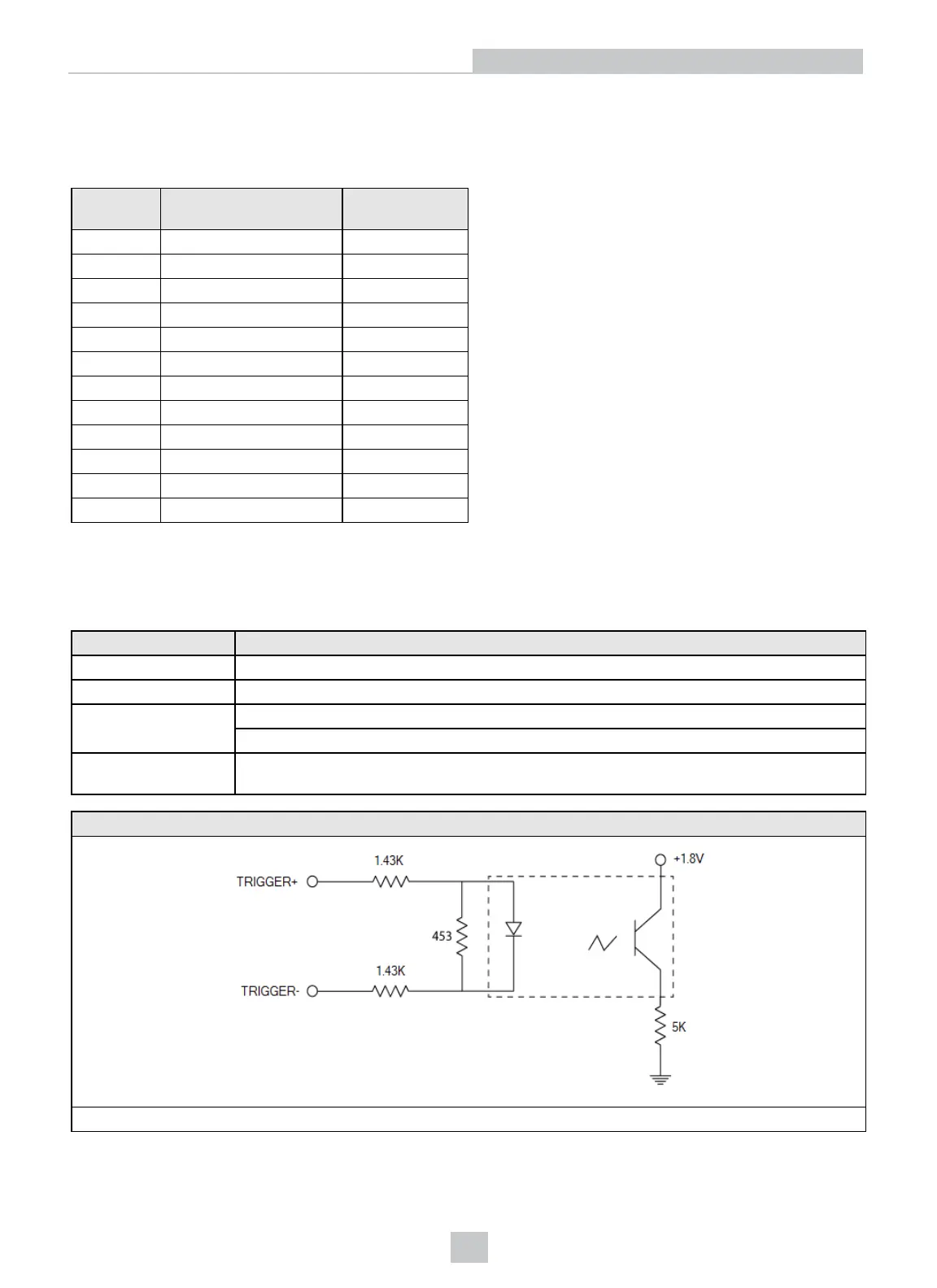
Trigger Circuit
30V max across the input pins - transition approx. 10V (Min.)
13
I/O Cable
 Loading...