I/O Cable
The Power and I/O cable provides access to trigger and inputs. You can clip unused wires short or use a tie made of
non-conductive material to tie them back.
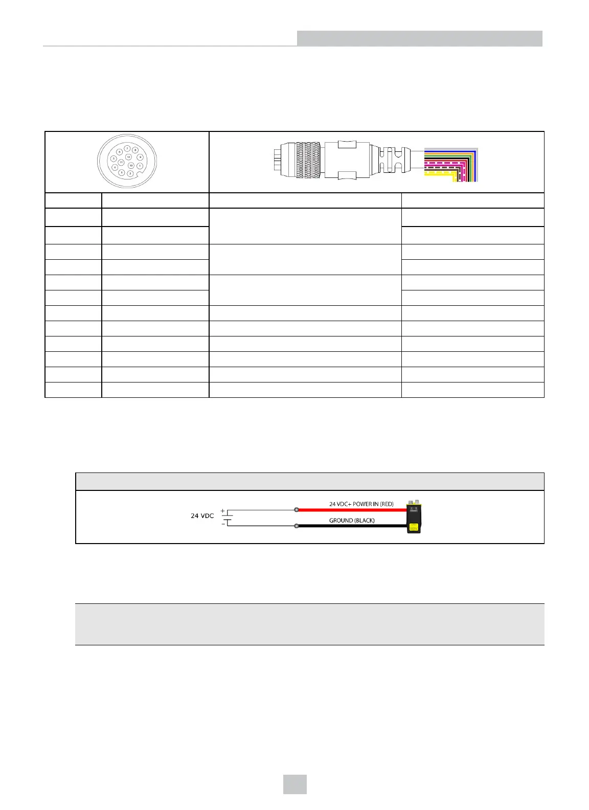
Pin # Signals Name Notes Color
1 PhB+
Encoder "B" input
(twisted pair)
Yellow
2 PhB- White/Yellow
3 PhA+ Encoder "A" input
(twisted pair)
Brown
4 PhA- White/Brown
5 Trig+ Trigger Violet
6 Trig- White/Violet
7 +24VDC Power Red
8 GND Ground Black
9 Laser+ Not Used Green
10 Laser- Not Used Orange
11 Ctrl+ Not Used Blue
12 Ctrl- Not Used Grey
When wiring the sensor, observe the following precautions:
l Use a listed power supply with an output rated 24VDC, at least 500 mA, and marked Class 2, Limited Power
Source (LPS). Any other voltage creates a risk of fire or shock and can damage the sensor. Refer to the following
wiring diagram for connecting the sensor to power:
Power
l Connect the cable or connector shield to earth ground.
l Pins 1, 2, 3, and 4 may be used for an encoder connection. The configuration that you set for your sensor using
the Cognex software determines how those lines are used.
Tip: Cognex recommends unused encoder connections be tied to ground. If encoder signal inputs are left
unconnected and your Cognex software is configured to use an encoder, the behavior of the encoder
counter is undetermined.
l Route cables and wires away from high-current wiring or high-voltage power sources to reduce the risk of
damage or malfunction from the following causes: over-voltage, line noise, electrostatic discharge (ESD), power
surges, or other irregularities in the power supply.
26
I/O Cable
 Loading...