266180-BIM-B-0209
Johnson Controls Unitary Products 3
RETURN AIR
In order for the furnace to work properly, a closet or alcove must have a
certain total free area opening for return air.
For Heating Only Furnace
Minimum 200 in
2
(1290 cm
2
) free area opening.
Use Return Grille 7900-287P/B, or any Return Grille with minimum 200
in
2
free area opening.
For A/C and HP Applications (Standard Blower)
Minimum 250 in
2
(1613 cm
2
) free area opening. Use accessary blower
package 3500-7901, or use Return Grille 7900-287P/B, 1FG0620BK
(hinged), or Louvered Door 3500-1581, 3500-5851 (bulk pack), or any
Return Grille with minimum 250 in
2
(1613 cm
2
) free area opening.
For A/C and HP Applications (Accessory Blower)
Minimum 330 in
2
(2129 cm
2
) free area opening. Use 5 ton blower
accessory 3500-7901 use Return Grille 1RF1025BK, 1FG0125
(hinged), or Louvered Door 3500-1591, 3500-5861 (bulk pack), or any
Return Grille with minimum 330 in
2
(2129 cm
2
) free area opening.
The return air opening can be located in a closet front door or a sidewall
above the furnace casing, or in a louvered door on the furnace. If open-
ing for the return air is located in the floor, side walls or closet door any-
where below furnace casing height, 6” (15.2 cm) minimum clearance
must be provided on the furnace side where return is located to provide
for proper air flow. See Figure 2. The 6” (15.2 cm) minimum clearance
is not required if there is a return grille installed above the furnace
height. This return grille cannot start more than three feet above the fur-
nace height.
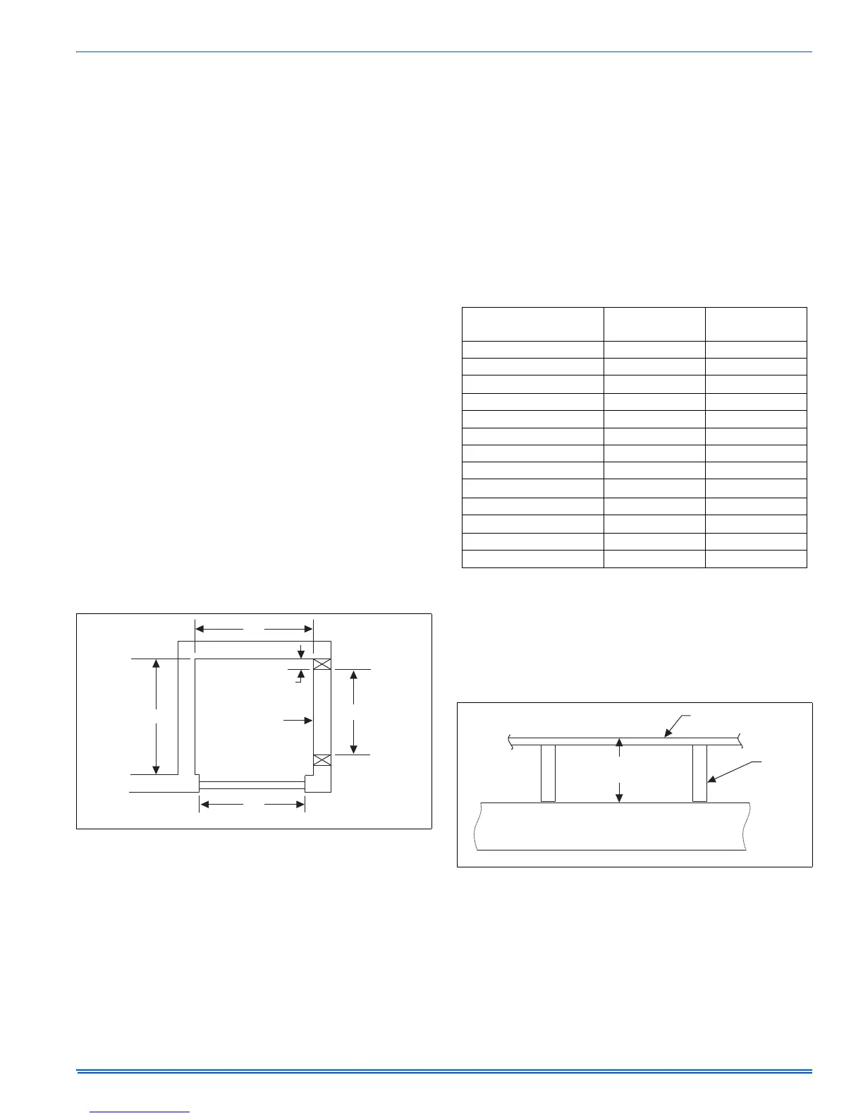
For Upflow installations, a closet 32” (81.3 cm) wide by 30” (76.2 cm)
deep with a 30” (76.2 cm) wide door is necessary. See Figure 3.
When installing furnace in a separate closet or room which is accessible
only through an outside door, a minimum of 200 in
2
(1290 cm
2
) free
opening for return air must be provided. The supply and return air must
be ducted, securely attached and be sealed to the furnace casing if
there are grilles in the outside door to the closet. Openings where ducts
pass through walls, the floor or the ceiling must be sealed to prevent air
leakage into or from closet and the living area.
Provisions shall be made to permit the return of circulating air from all
rooms and living spaces, except the bathroom(s) to the circulating air
supply inlet of the furnace. Failure to comply may cause improper heat-
ing and may cause the furnace to cycle on the limit.
DUCT SYSTEM DESIGN
Electric furnace is designed to operate at a given static pressure.
In order to assure proper air flow through the furnace, the distribution
system must be designed so that the static pressure external to the fur-
nace does not exceed the static pressure rating shown on the furnace
rating plate.
The number, size and placement of registers should be such that even
distribution of heat is provided throughout the home.
SECTION IV: DOWNFLOW FURNACE
INSTALLATION
7900 SERIES DUCT CONNECTOR
We have designed our duct connector to eliminate a sub-base require-
ment. Table 1 will help you in deciding the part number of the duct con-
nector you need.
Provide adequate clearance for servicing.
1. Locate furnace conveniently away from wall facing or partitions to
permit easy removal of components.
2. A six (6) inch space minimum should be maintained between the
furnace and closet door when door is used for return air.
3. Two (2) feet of space must be available in front of furnace for
future servicing (blower, element or furnace removal, etc.).
- Indicates connector above or below could be used depending on
tolerance in floor to duct dimension.
- Indicates connector above could be used depending on toler-
ance in floor to duct dimension.
- Indicates connector below could be used depending on tolerance
in floor to duct dimension.
DUCT CONNECTORS (7990 SERIES)
These duct connectors are for connecting the furnace to an under the
floor supply duct system. The furnace may be installed on combustible
flooring without a separate sub-base.
FIGURE 2: Upflow Closet Clearances
30”
32”
30”
Wide Door
Closet
25-1/2””
Return Air
Pass Through
Frame Width
1-5/8” Min., 2-3/8 Max.
TABLE 1:
Duct Connector for Electric Furnaces
FLOOR TO
DUCT DIMENSIONS
FINGERED
STYLE
SCREW
TAB STYLE
1” (2.54 cm) 7990-6211 7990-6011
2” (5.1 cm) 7990-6221 7990-6021
3” (7.6 cm)
4” (10.2 cm) 7990-6241 7990-6041
5” (12.7 cm)
6” (15.2 cm) 7990-6261 7990-6061
7” (17.8 cm) 7990-6271 7990-6071
8” (20.3 cm) 7990-6281 7990-6081
9” (22.8 cm)
10” (25.4 cm) 7990-6301 7990-6101
11” (282 cm)
12” (30.5 cm) 7990-6321 7990-6121
13” (33 cm)
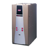
FIGURE 3: Duct Connector Depth (7990 Series)
Duct Connector
Depth
Floor
Floor
Joist
SUPPLY DUCT