266180-BIM-B-0209
4 Johnson Controls Unitary Products
INSTALLATION OF SCREW ATTACHMENT DUCT
CONNECTOR (7990 SERIES)
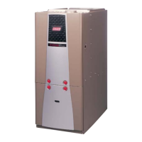
1. Make floor cut out as shown in Figure 5.
2. Determine the depth of the floor cavity from the surface of the floor
to the top of the supply air duct and select the appropriate duct
connector from the chart.
3. Place locating bracket (supplied with the duct connector) to the
back edge of the floor opening. See Figure 6.
4. Apply a water based duct sealant to the 1/2" supply duct attach-
ment flange of the duct connector.
5. Determine which of the four positions the duct connector best cen-
ters over the supply duct and insert it through the floor cutout.
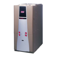
6. When properly aligned with the supply duct, secure the duct con-
nector to the floor with nails, flat head screws or staples.
7. Use screws as required to secure duct connector to supply duct.
8. Cut out the opening to the supply duct. If sealant was not used, the
installer should tape the mating flanges to provide a good air seal.
NOTE: Duct sealant and tape must be classified as meeting HUD Stan-
dard 3280.715, U.L. Standard 181A.
INSTALLATION OF TAB ATTACHMENT DUCT
CONNECTOR (7990 SERIES)
1. Make floor cut out as shown in Figure 5.
2. Determine the depth of the floor cavity from the surface of the floor
to the top of the supply air duct and select the appropriate duct
connector from the chart.
3. Place locating bracket (supplied with the duct connector) to the
rear of the floor area for the furnace. See Figure 7.
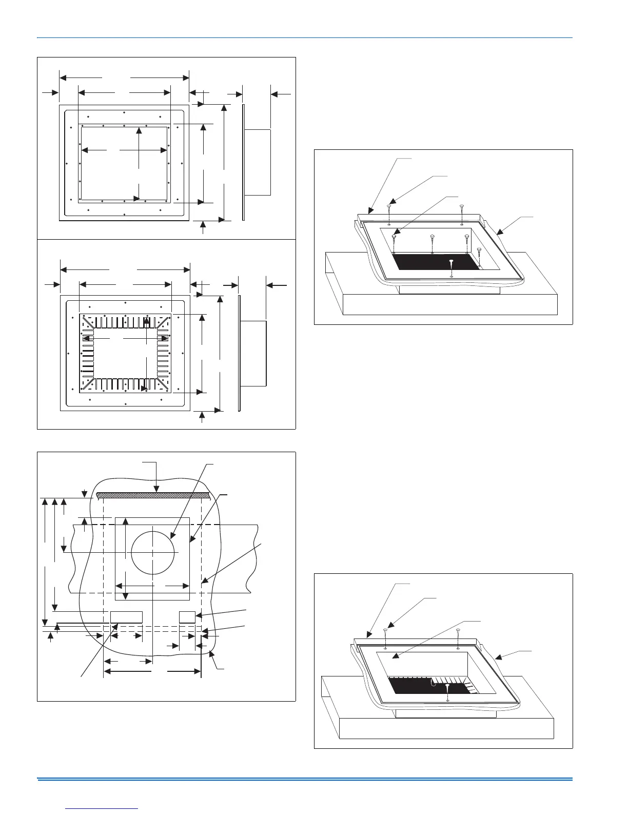
FIGURE 4: Duct Connector Dimensions (7990 Series)
FIGURE 5: Recommended Floor Cut-out (7990 Series)
12
13
11
14
See
Chart
18-3/4
18-3/4
2-3/8
4-3/8
2-3/8
SCREW ATTACHMENT
2-3/8
13
11
14
See
Chart
12
DUCT
CUTOUT
DIMENSIONS
DUCT CONNECTORS FOR
TAB ATTACHMENT
18-3/4
2-3/8
18-3/4
2-3/8
4-3/8
2-3/4
Min.
23-1/4
20-1/2
9-7/8
2-1/8
1-3/8
6-3/8
9-3/4
20
3-1/4
1-1/8
15
15
1
Rear Wall
of Enclosure
Ceiling Cut-out
for Roof Jack
Floor Cut-out
for Duct Connector
Furnace
Outline
Optional
Electric
Entrance
Floor
Future Refrigerant
Line Entrance
FIGURE 6: Duct Connector Screw Attachment (7990 Series)
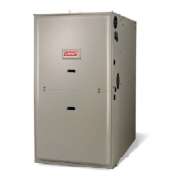
FIGURE 7: Duct Connector Tab Attachment (7990 Series)
Locator Bracket
Nails, Flat Head Screws
or Staples
Screws
Floor
SUPPLY DUCT
Bend Tabs Under Duct
Opening to Secure to
the Supply Duct
SUPPLY DUCT
Locator Bracket
Nails, Flat Head Screws
or Staples
Floor