266180-BIM-B-0209
Johnson Controls Unitary Products 7
Casing or cabinet must be permanently grounded in accordance with National Electrical Code or other applicable codes.
1. Approved for Single Branch Circuit Service Only.
TABLE 3:
EB Series Blower Performance
Static Pressure (inches of w.c.) 0.0 0.1 0.2 0.3 0.4 0.5 0.6 0.7 0.8
Low Speed - Heating Speed
Models EB10, 12, 15
CFM (STD. Air) 945 936 936 924 915 889 870 813 705
Medium Speed - Heating Speed
Models EB17, 20, 23
CFM (STD. Air) 1160 1145 1145 1140 1129 1109 1073 1027 935
Medium High - with A-Coil in place CFM (STD. Air) 1340 1317 1290 1252 1208 1158 1095 1021 876
High - with A-Coil in place CFM (STD. Air) 1573 1534 1490 1435 1369 1309 1237 1135 1019
TABLE 4:
Electrical Data
MODEL NUMBER EB23C EB20C EB17C EB15C EB12C EB10C
D.O.E.
Output
240 VAC
60 Hz.
1 Phase
BTU 77,000 67,000 56,000 51,000 39,000 34,000
kW 22.6 19.6 16.4 15.0 11.4 10.0
OUTPUT
CAPACITY
230 VAC
60 Hz.
1 Phase
BTU 71,000 61,000 52,000 47,000 36,000 31,000
kW 20.8 17.9 15.2 13.8 10.6 9.1
220 VAC
60 Hz.
1 Phase
BTU 65,000 57,000 48,000 43,000 33,000 29,000
kW 19.1 16.7 14.1 12.6 9.7 8.5
Element Capacity
@ 240 VAC
kW 21.6 19.2 16.0 14.4 11.2 9.6
Amps 90.0 80.0 66.7 60.0 46.7 40.0
Motor Amps @ 240 V. 4.0 Maximum
Circuit Load Amps
@ 240 V.
CKT 1 47.3 44.0 47.3 44.0
50.7
1
44.0
1
CKT 2 46.7 40.0 23.4 20.0 NA NA
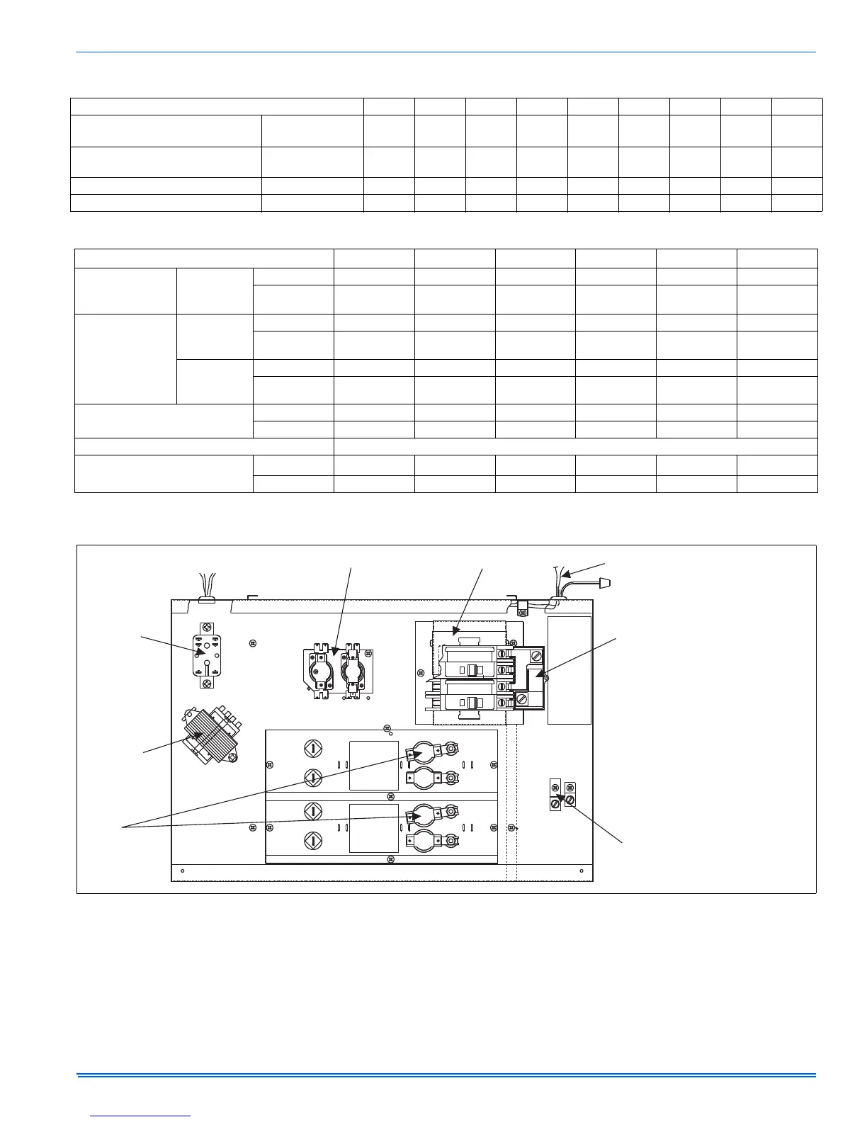
FIGURE 12: Control Box
Sequencers
Circuit Breakers
Thermostat
Wires
Blower
Relay
Transformer
Limit
Switches
Ground
Lugs
3500-378P* Jumper
Bars (For Single
Branch Circuit Service)
NOTE:
As Shipped, the Jumper Bar Assembly
is Set-up for Bottom Entry. For Side
Entry, the Top Lug can be Removed and
Re-positioned, as Shown, to Provide
Proper Wire Bending Clearances.