266180-BIM-B-0209
8 Johnson Controls Unitary Products
SECTION V: THERMOSTAT INSTALLATION
The adjustable heat anticipator in the thermostat is pre-set at 0.4 Amps.
This setting should be checked at the time of installation.
In some cases the thermostat may be a “self-setting" type in which case
no amp setting will be found on the thermostat, eliminating the need for
any field adjustment.
Thermostat should be located on an inside wall in an open area to more
closely regulate average room air, preferably, where there is air move-
ment back to furnace. Care should be used to locate thermostat away
from hot air discharge openings, lights, etc. Locating height of thermo-
stat is important. Thermostat should be located 52” to 66” (132 - 167.6
cm) above the floor. This is sometimes called the comfort zone.
If a condenser with its own Transformer shares a Heat/Cool Thermostat
with this furnace, use a thermostat with isolating contacts to prevent
interconnection of Class II 24 Volt Systems.
Cycle furnace using the thermostat to make sure it will operate cor-
rectly.
Maintenance and operating instructions are in the customer envelope
accompanying the furnace. Give the customer envelope to the home
owner.
For personal safety be sure to turn the electrical power OFF at the
household service box and at the furnace circuit breakers before
attempting any service or maintenance operations. Homeowners
should never perform any maintenance which requires opening
electric box door.
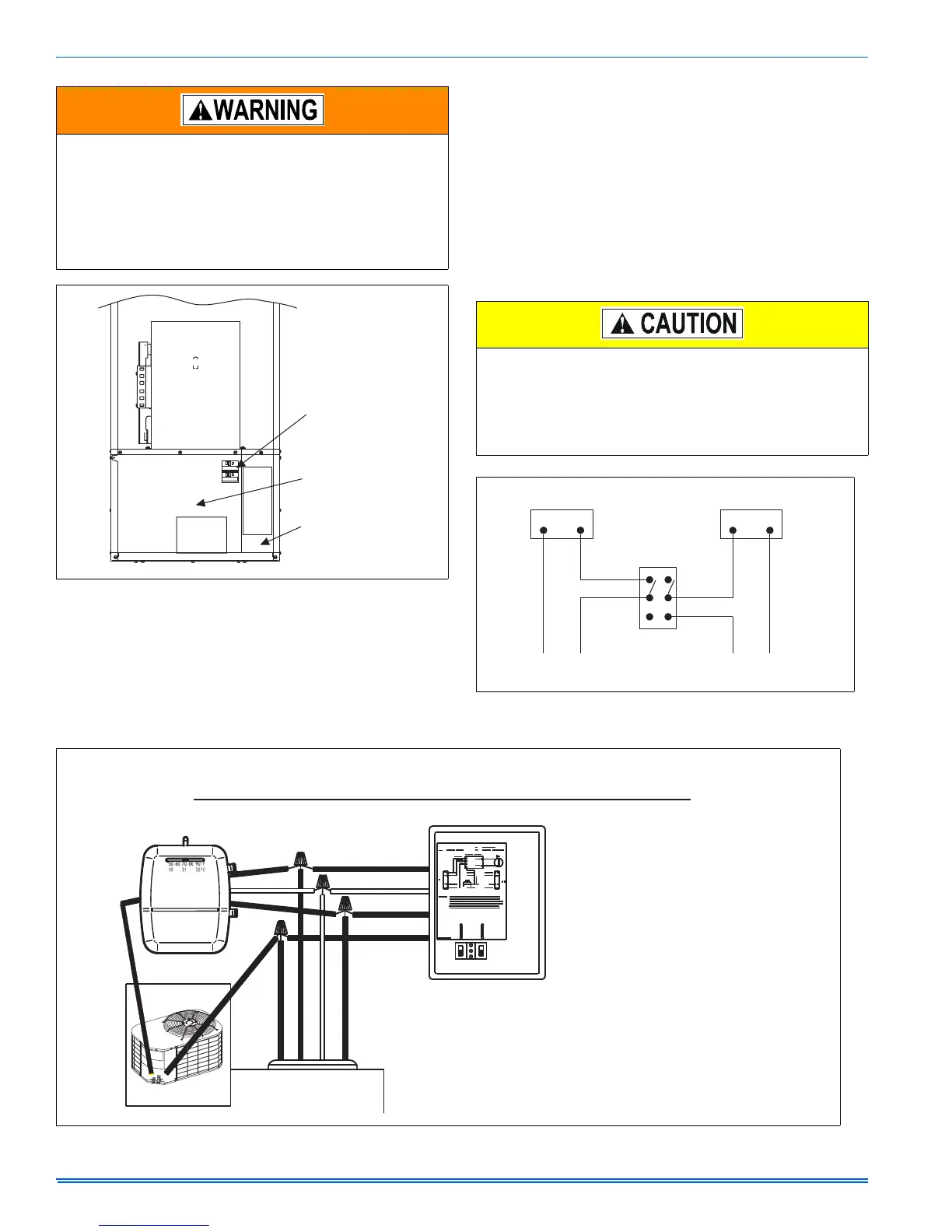
Furnace is equipped with a protective shield over field wiring con-
nection. When field wiring is completed, shield must be replaced to
prevent hazard of electrical shock when using furnace disconnect.
(See Figure 13.)
FIGURE 13: Field Wiring Shield
Circuit
Breakers
Electric
Panel
Field Wiring
Protective
Shield
BLOWER
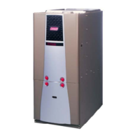
When using separate thermostats, a thermostat interlock system
must be provided to prevent simultaneous operation of the furnace
and air conditioner. Simultaneous operation can result in coach
overheating, equipment damage and energy waste. (See Figures
14 and 15.)
Do not connect Yellow wire to thermostat until an outdoor unit is
installed.
FIGURE 14: Thermostat Wiring
Cooling
Thermostat
Heating
Thermostat
To
Air Conditioner
To
Furnace
Double Pole
Double Throw Switch
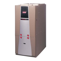
FIGURE 15: Thermostat Wiring
DELUXE
BLEND AIR
II
FRESH
AIR
OFF
AUTO
ALARM
RED
RED
WHITE
WHITE
GREEN
GREEN
BLACK
BLACK
BLACK
RED
WHITE
GREEN
YELLOW
WIRES FROM FURNACE
NOT FACTORY
INSTALLED
STANDARD OR DELUXE
BLEND AIR CONTROL BOX
THERMOSTAT WIRING SCHEMATIC FOR: BLEND AIR AND FURNACE
The EB*C* Furnaces are A/C ready.
All furnaces installations should include a minimum of four conductor thermostat
wiring to accommodate future air conditioning installations.
Four-conductor wire is required for thermostat connection.
Attach the 4 low voltage wires extending from the control box as follows:
RED RED
WHITE WHITE
GREEN GREEN
BLACK
YELLOW
1. wire from Furnace to thermostat wire.
2. wire from Furnace to thermostat wire.
3. wire from Furnace to thermostat wire.
4. wire from Furnace to condensing unit contactor.
5. Thermostat wire to condensing unit contactor.