Do you have a question about the Colortrac SC Series and is the answer not in the manual?
Anti-static and cable.
HB Lead, or similar
To remove and fit M5 nuts.
or 1.5mm Hex Key
PZ1 x 80mm length.
PZ0 x 60mm length.
3mm blade x 65mm length (approx.)
6mm blade (approx.)
Flat nosed pliers, short serrated.
(no shown)
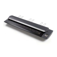
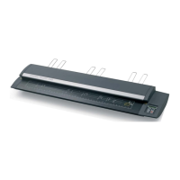
Ensure power and USB cables are disconnected. Position scanner on stable platform.
Lists tools required for the modification procedure, including screwdrivers and pliers.
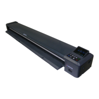
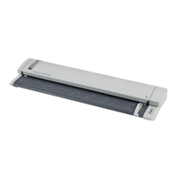
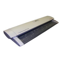
The Colortrac SC Series Technical Manual provides comprehensive instructions for the maintenance and modification of Colortrac SC Series scanners, including the SC25 Xpress, SC36 Xpress, SC42 Xpress, and their MFP (multi-function peripheral) variants (SC25 mfp, SC36 mfp, SC42 mfp). This manual specifically details the "Power Switch Modification" procedure, which involves bypassing the physical power switch for certain models.
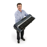
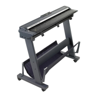
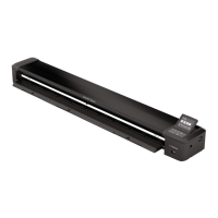
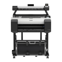
The Colortrac SC Series scanners are designed for large-format document scanning, catering to various professional needs. The "Xpress" models likely emphasize speed and efficiency in scanning, while the "mfp" models integrate additional functionalities, typically including printing and copying capabilities, making them versatile tools for offices and design studios. These scanners are engineered to capture high-quality digital images of physical documents, ranging from technical drawings and maps to posters and artwork. The core function involves feeding a document through a scanning path where optical sensors capture its image, which is then processed and transferred to a connected computer. The internal components, such as the main board and control board, manage the scanning process, data transfer, and power distribution. The modification described in this manual aims to alter the power management system, specifically the physical power switch, by introducing a bypass link. This suggests a potential change in how the device is powered on or off, possibly to enable a different power-on behavior or to address a specific technical requirement or issue related to the original power switch design. The modification effectively creates a permanent connection where the power switch would normally interrupt the circuit, meaning the device might power on automatically when connected to a power source, or its power state might be controlled externally rather than through a physical switch on the unit itself.
The Colortrac SC Series scanners are designed for ease of use in professional environments. While the manual focuses on internal modifications, the underlying design implies features that facilitate document handling and scanning operations. Users would typically feed documents into the scanner, and the device would automatically detect the document and initiate the scanning process. The "Xpress" designation suggests features like fast scanning speeds, potentially with advanced document handling capabilities to prevent jams or misfeeds. The "mfp" variants would offer integrated printing and copying functions, allowing users to perform multiple tasks from a single device, streamlining workflows. The scanners are likely compatible with various operating systems and scanning software, providing a user-friendly interface for controlling scan settings, previewing images, and saving files in different formats. The robust construction, indicated by the need for specific tools for maintenance, suggests a durable design capable of handling continuous operation in demanding environments. The presence of a calibration sheet, mentioned in the unboxing procedure, highlights the importance of maintaining scan accuracy and color fidelity, which are crucial for professional applications. The modification itself, by bypassing the power switch, could simplify the power-on sequence for users, potentially allowing the device to be controlled by a master power switch for an entire workstation or to power on automatically upon system boot-up, depending on the specific implementation. This could be particularly useful in integrated systems where the scanner is part of a larger setup.
The technical manual is primarily a maintenance guide, detailing a specific modification. It outlines a structured procedure for accessing the internal components of the scanner, emphasizing safety precautions such as disconnecting power and USB cables and ensuring the scanner is on a stable platform. The required tools, including screwdrivers, nutdrivers, pliers, and an anti-static wristband, indicate that maintenance involves working with delicate electronic components and requires careful handling to prevent damage from electrostatic discharge. The step-by-step instructions for disassembling the scanner, such as removing the top lid cover, main board cover, and disconnecting cables, highlight the modular design of the device, which facilitates repair and component replacement. The modification itself involves disconnecting earth cables from the power switch and installing a "modification link" consisting of spade terminals on a short length of wire. This suggests that the power switch is being permanently bypassed, and the earth connection is being rerouted. The instruction to feed the modification link under the lip of the main board cover indicates attention to detail in cable management to prevent catching or damage during reassembly. The reassembly process is described in reverse order, ensuring that all components, including the main board cover, control board bracket, and top lid cover, are correctly seated and secured. The final step of marking off number '9' on the tag matrix label at the rear of the scanner serves as a crucial maintenance record, indicating that this specific modification has been completed. This systematic approach to maintenance ensures that any modifications or repairs are performed correctly and documented, which is essential for troubleshooting and future servicing. The detailed unboxing and re-packing instructions also serve as a guide for safe transportation and handling of the scanner, ensuring its integrity during shipping or relocation. The emphasis on careful handling of suppressor leads on the main board cover further underscores the delicate nature of the internal electronics and the need for precision during maintenance.
| Scan Speed (Color) | Up to 5.5 inches per second (140 mm/sec) |
|---|---|
| Color Depth | 48-bit |
| Supported Media Types | Paper |
| Dimensions | Varies by model |
| Weight | Varies by model |