CALOR 40 Manual Page 15 (total 27) COMAC CAL s.r.o.
Avoid making kinks in the cable or in individual conductors and do not allow their mutual
crossing in the terminal board area and always use a separate cable grommet for power
supply lead. The flow sensor shielding wire must not be in direct (electrically conductive)
contact with the interior metallic cover of the meter.
Use pieces of cable or plastic pins to plug up the unused grommets (impermeability).
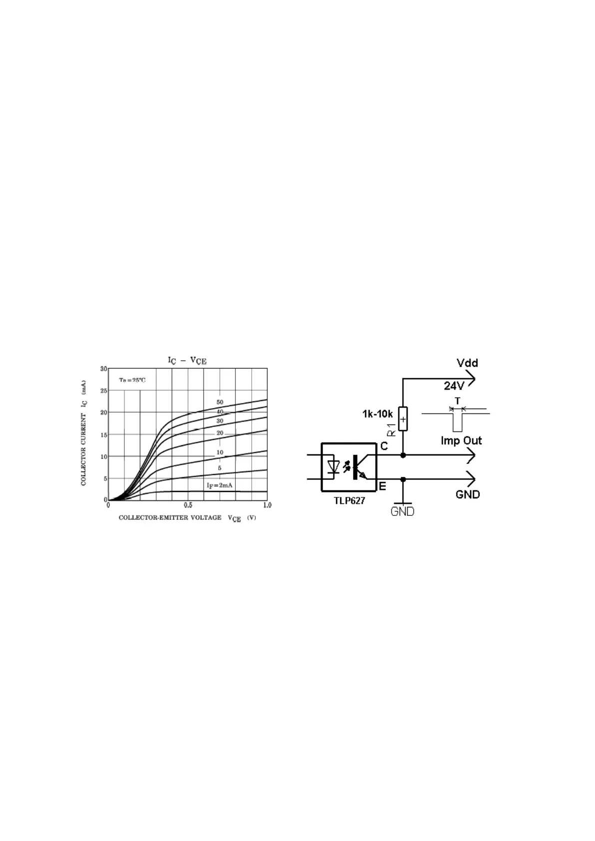
E & V pulse outputs
The output of energy and volume pulses is implemented by an optocoupler with an NPN
switching transistor. Limit parameters of this optocoupler are 80V/100mA/100mW max.
The volume and energy pulse output serves for remote transmission of volume and energy
pulses. The conversion constant is arbitrarily adjustable (float data type) using user software.
Setting must be carried out in such a manner that fout<15Hz.
The optocoupler load should be selected in such a way that its limit parameters cannot be
exceeded:
Load characteristic (I
f
= 2.5mA) Wiring example
Owing to CTR≈100%, it is necessary to select the collector current of 2.5mA at the most.
Pulse inputs
As a standard, the meter is equipped with 2 pulse inputs isolated by optocouplers. The 560R
resistor is inserted in the input. Max. permissible current of the LED is 50mA, which makes it
possible to connect the input up to 24V voltage directly. The conversion constant is arbitrarily
adjustable (float data type) using user software and fin<1.2kHz must be accepted.
Current output
The CALOR40 has a sixteen-bit D/A - converter with data update approx. every second. The
converter is isolated from the meter itself by means of optocouplers. The current loop is