CALOR 40 Manual Page 12 (total 27) COMAC CAL s.r.o.
Wiring system
This works can be done just by a competent person with the appropriate electro technical
qualification in accordance with terms of Law Regulation!!!
The warranty for errors resulting from incompetent implementation of operations described
below becomes null and void!!!
Turn off the power every time before the Evaluation Unit is opened!!!
It must be remembered that Electronic Evaluation Unit and flow meter sensor are whole
system that is uniquely paired and calibrated. Always assure that serial numbers of both parts
are identical!!!
Meter wiring
In the event of the separate construction, the special cable to connect the meter must not be
lengthened or shortened.
The signal cable of the separated inductive flow sensor cannot be run in parallel even partially
with cables for line voltage distribution or close to motors, electromagnets, contactors,
frequency converters, and similar sources of electromagnetic disturbance. In inevitable cases
it is necessary to run the cable inside the ferrous and grounded conduit.
In order to ensure the impermeability of the evaluation unit cover, it is necessary to keep the
gasket intact and clean and always covered with grease (the impaired seal should be replaced
immediately). If the cable grommets are not stemmed, it is necessary to do so.
Evaluation unit
The evaluation unit is delivered for 230V / 50÷60Hzpower supply.
The signal inputs and outputs of the flow meter may only be connected to devices where
personal accident protection is ensured by safety extra-low voltage and where the generated
voltages do not exceed the limits specified for the safety extra-low voltage.
Evaluation unit wiring
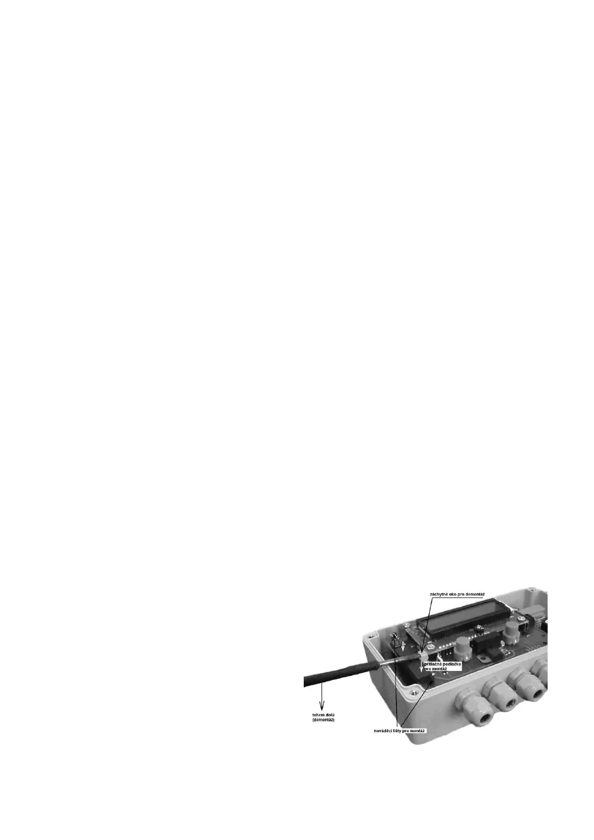
The terminal board for connection of individual interconnecting cables is located inside the
temperature meter cover. The cover can be removed after four clamp bolts are unscrewed.
The upper part of the meter should be removed as shown in the figure below. The terminal
board is found on the lower part.
Upper part removal procedure:
1) Insert a screwdriver in the lug for
removal.
2) By pulling the handle downward
disengage the upper part carefully
from guides.
Upper part assembly procedure:
1) Put the upper part onto the guides.
2) By pressing gently onto the thrust
washer, push the upper part
connector into the lower PCB.